Drivable eye bolt

a technology of eye bolts and threads, which is applied in the direction of threaded fasteners, screws, fastening means, etc., can solve the problems of cumbersome threading procedure, time-consuming and laborious, and inability to easily rotate the eye bolts, etc., and achieves the effect of simple threading into the structur

Inactive Publication Date: 2013-03-07
AUCHEY JED
View PDF8 Cites 15 Cited by
  • Summary
  • Abstract
  • Description
  • Claims
  • Application Information

AI Technical Summary

Benefits of technology

[0004]It is, therefore, a primary object of the present invention to provide a novel and improved eye bolt which is simple to insert into a structure without need for special tools.
[0005]It is also an object of the present invention to provide a novel and improved eye bolt which is simple to start without need for a pilot hole and which can be rapidly inserted utilizing a single readily available tool.

Problems solved by technology

However, use of a bar for rotating the eye bolt is slow and clumsy, particularly if a large number of eye bolts are to be inserted in place.
However, such special tools are expensive to acquire and, typically, not readily available.
It will be appreciated that the procedure for threading an eye bolt into a structure is cumbersome, time consuming and requires several different tools.
Moreover, unless a pilot hole is first drilled, the starting process can be frustrating and difficult since hammering is likely to deform the loop end of the eye bolt.
Of course, drilling the pilot hole requires additional time and additional tools.

Method used


Image

  • Drivable eye bolt
  • Drivable eye bolt
  • Drivable eye bolt

Examples


Embodiment Construction

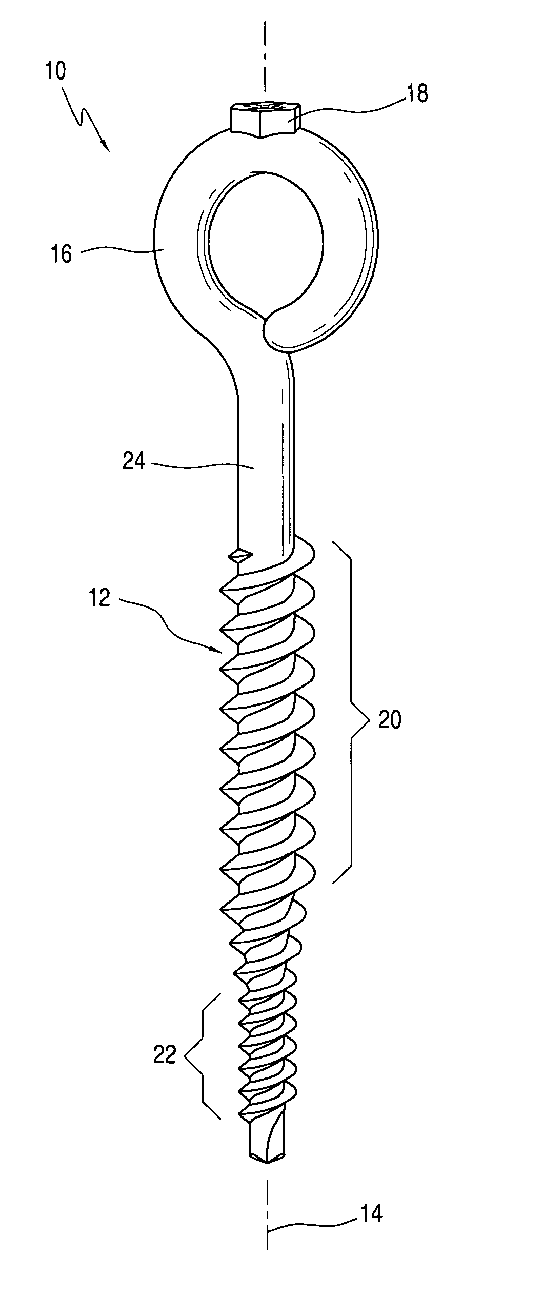
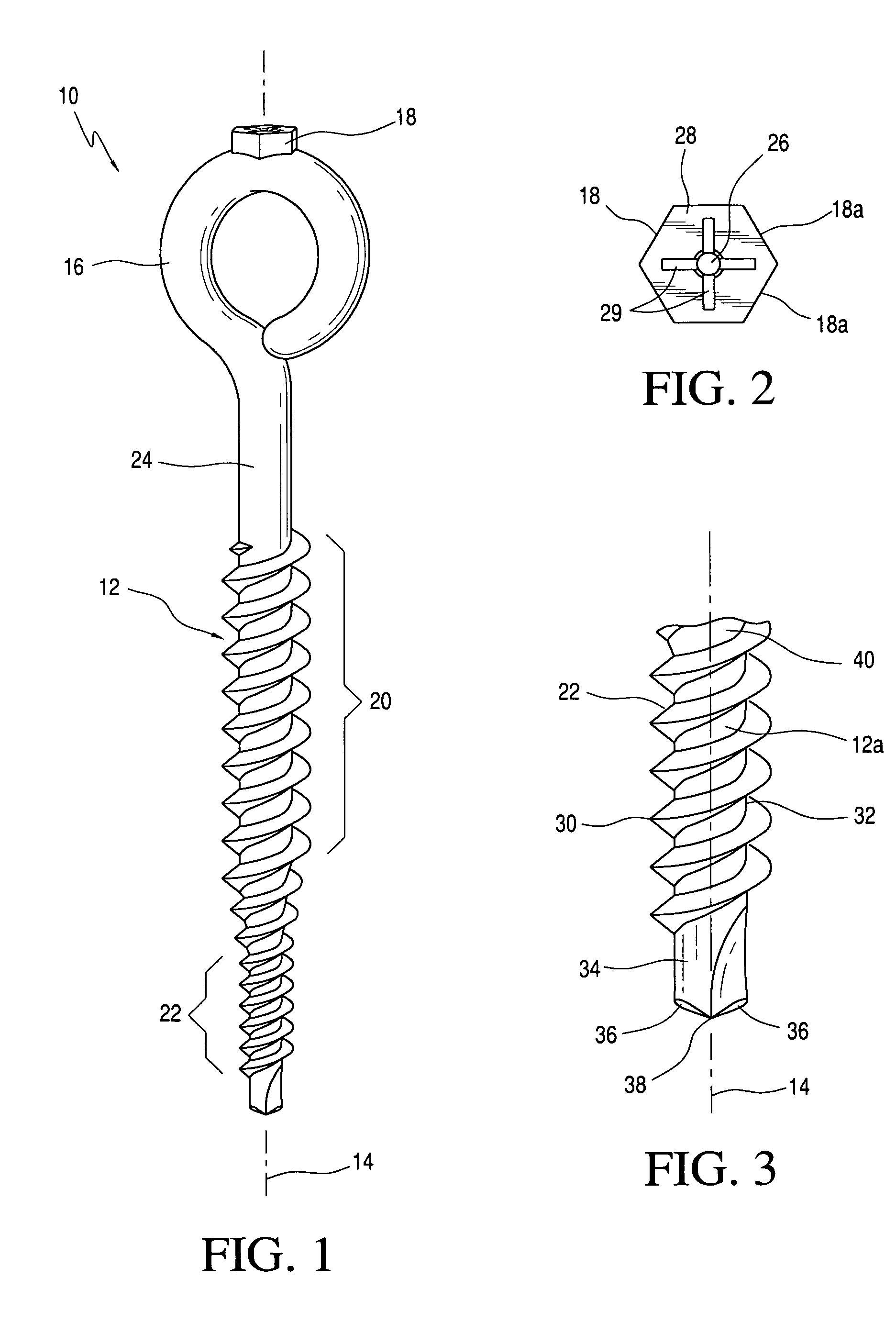
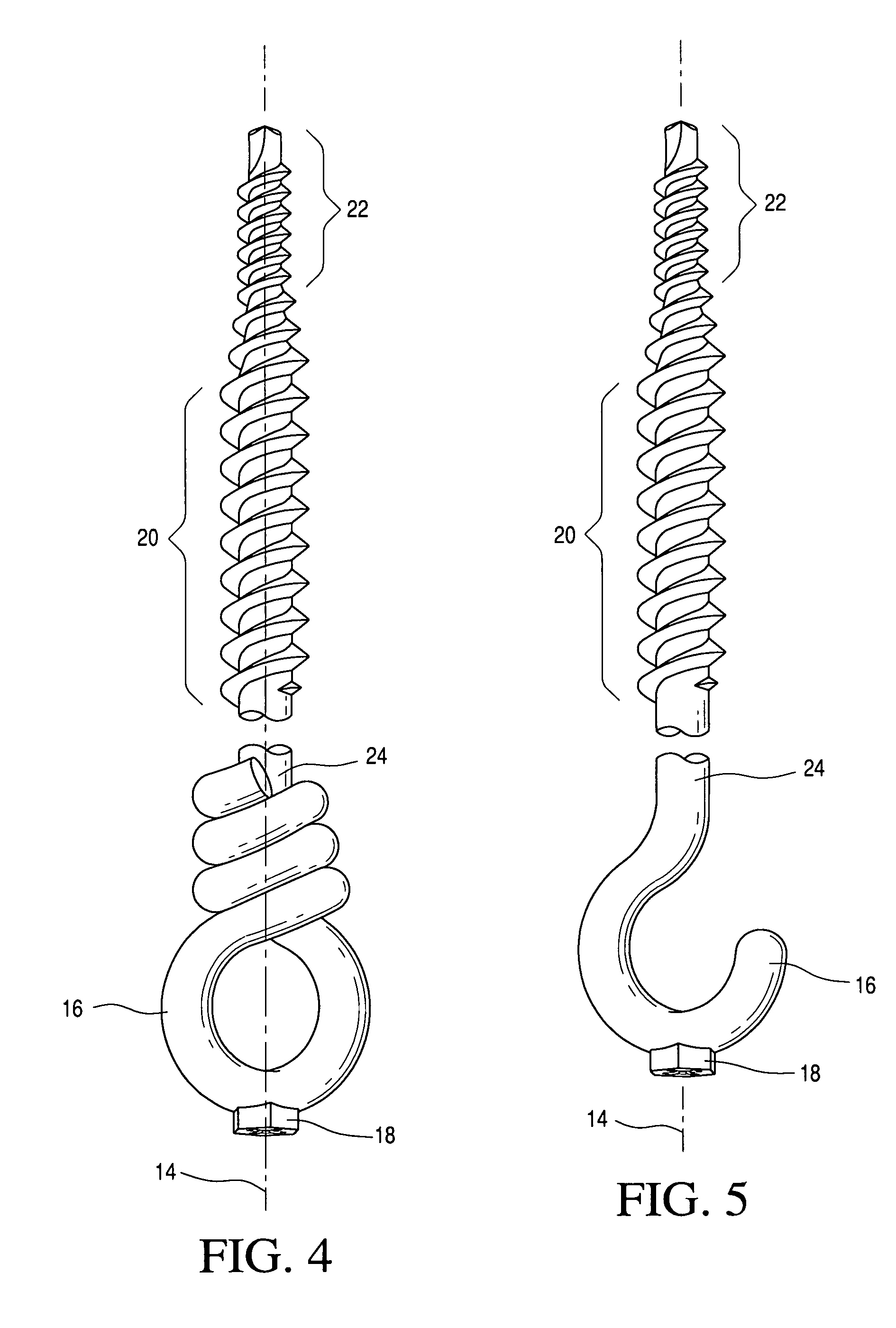
[0025]Referring to FIG. 1, there is shown one embodiment of the eye-bolt of the present invention. Eye bolt 10 includes a shank 12 having a longitudinal axis 14, a loop portion 16, a driving head 18 mounted, e.g., by welding, forging, on loop portion 16 remote from shank 12 and coaxial with shank 12 and a threaded portion 20 along shank 12. In one form of the invention, shank 12 is provided with a self drilling and self tapping portion 22 at the end of shank 12 remote from loop portion 16. Shank 12 may be completely threaded along its length between self drilling and tapping portion 22 and loop portion 16 or threaded portion 18 may terminate short of loop portion 16 for defining a smooth shank portion 24 between the end of threaded portion 20 and loop portion 16. Threaded portion 20 of shank 12 may have a substantially cylindrical external diameter or its diameter may gradually taper downwardly toward a smaller diameter or a point at its end remote from loop portion 16. Loop portion...


PUM


Abstract

An eye bolt has an elongate threaded shank having a longitudinal axis and a loop projection, such as a circular loop, extending from one end of the shank and a driving head rigidly mounted on the loop projection coaxially with the axis. To facilitate insertion into a material, the shank may include a self drilling and self tapping portion at the opposite end portion of the shank. A rotational driving force applied to the driving head causes the self drilling and self tapping portion to drill a hole in the material into which the threaded portion on the shank is screwed.

Description

FIELD OF THE INVENTION[0001]The present invention relates to eye bolts and, more particularly, to eye bolts which are simple to start without need for a pilot hole and drivable without need for special tools or attachments.BACKGROUND OF THE INVENTION[0002]Eye bolts with lag threads are commonly used to hang loads from overhead locations, such as beams and ceilings, as well as from walls, trees and other structures. In the usual procedure, the worker will either hammer the eye bolt into the structure (e.g., wood) in order to grab a few threads, or he will pre-drill a pilot hole. In either case the threaded shank of the eye bolt is thereafter manually screwed into the structure material using conventional tools such as wrenches or pliers to grasp the loop of the eye bolt or by insertion of a short bar through the eye of the bolt. The bar is then operated to rotate the eye bolt until the bolt is securely in place. Any type of short bar which fits through the loop of the bolt is satisfa...

Claims


Application Information

Patent Timeline
Patent Type & Authority Applications(United States)
IPC IPC(8): F16B25/10F16B23/00
CPCF16B23/0023F16B45/00F16B25/103F16B45/002
Inventor AUCHEY, JED
Owner AUCHEY JED
Why Eureka
Try Eureka