Transmission apparatus, transmission method and transmission system

a transmission apparatus and transmission system technology, applied in the direction of transmission, electric apparatus, depolarization effect reduction, etc., can solve the problems of leakage and signal, and achieve the effect of improving the efficiency of removing components of signals different from targets included in targets

Inactive Publication Date: 2013-03-07
NEC CORP
View PDF26 Cites 2 Cited by
  • Summary
  • Abstract
  • Description
  • Claims
  • Application Information

AI Technical Summary

Benefits of technology

[0034]The present invention has an effect that the efficiency of removing components of a signal different from a target signal included in the target signal is improved.

Problems solved by technology

In the cross polarization transmission method, there are cases where a wireless signal having a polarized wave different from a target line leaks out to a received signal due to the limitation of the polarized wave separation performance of an antenna, a change in a propagation environment and the like.
However, in fact, due to a change in the transmission condition of a transmission line and limit of the performance of an antenna, interference of a signal occurs between polarizations by the routes of the dashed lines of FIG. 4 between Main Master and Sub Master.

Method used


Image

  • Transmission apparatus, transmission method and transmission system
  • Transmission apparatus, transmission method and transmission system
  • Transmission apparatus, transmission method and transmission system

Examples


first exemplary embodiment

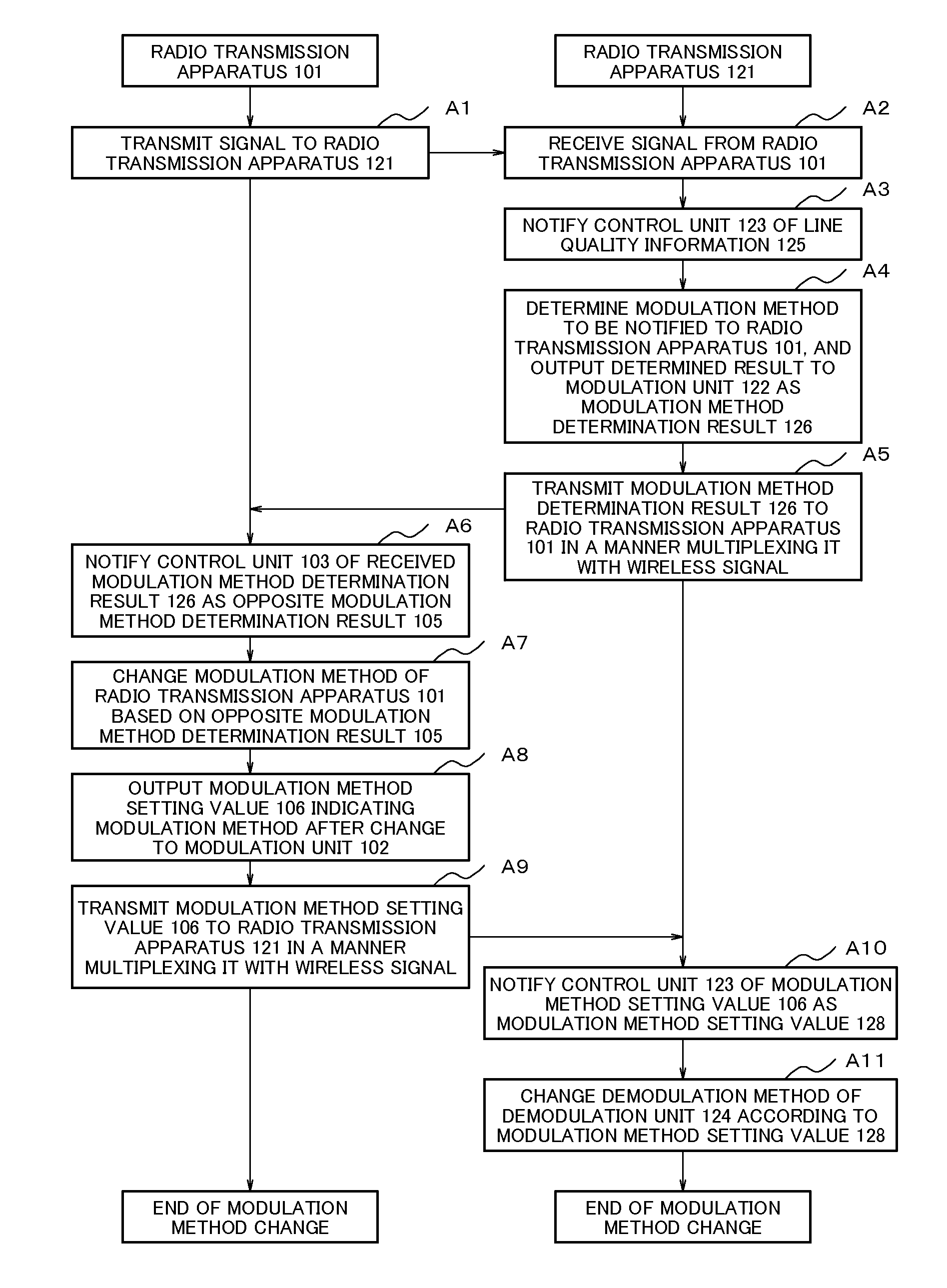
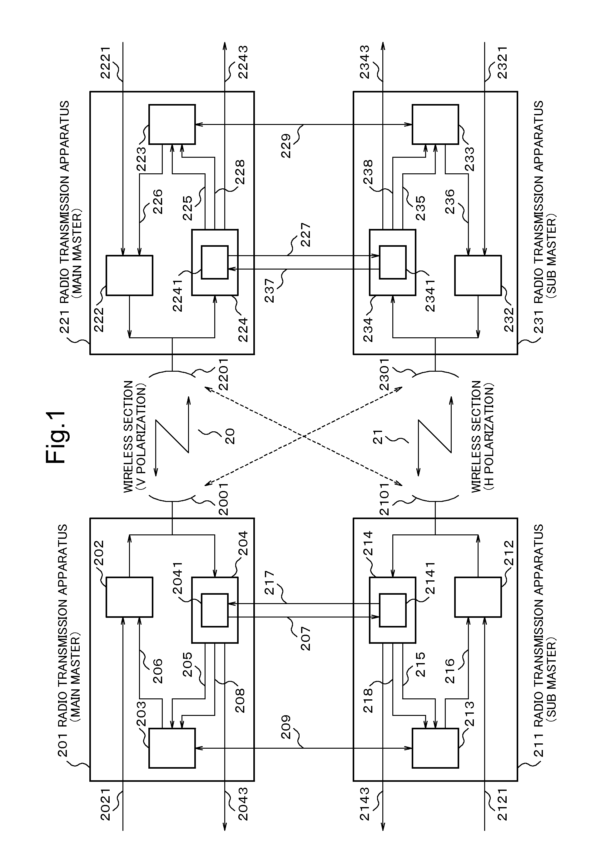
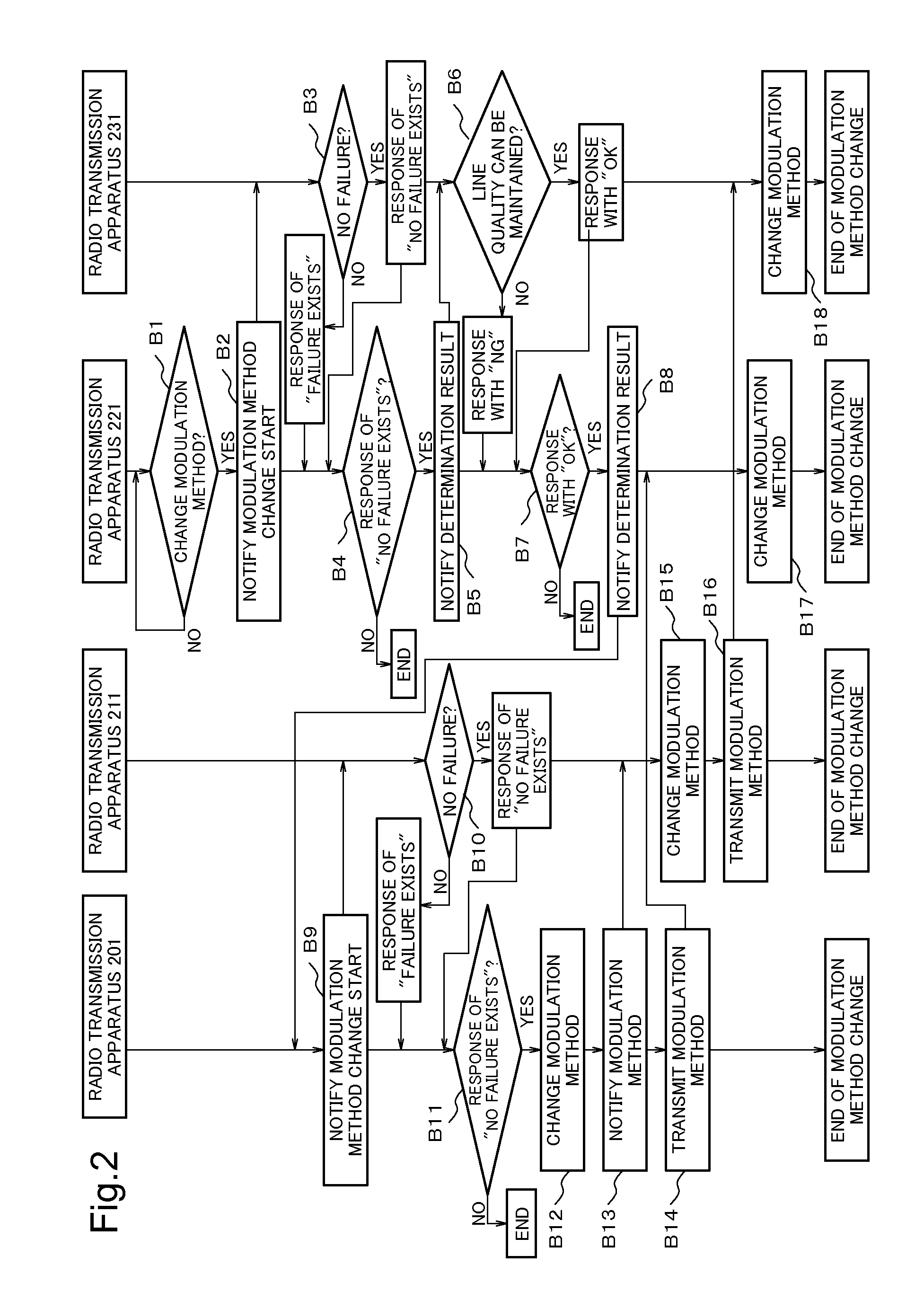
[0040]FIG. 1 is a diagram showing a structure of a radio transmission system of the first exemplary embodiment of the present invention. A radio transmission system shown in FIG. 1 includes radio transmission apparatus 201, 211, 221 and 231 each equipped with the XPIC function and the adaptive modulation function.

[0041]In FIG. 1, the radio transmission apparatus 201 and 221 are the Main Masters, and perform wireless transmission in a wireless section 20 by V polarization. The radio transmission apparatus 211 and 231 are the Sub Masters, and operate in a manner being synchronized with the radio transmission apparatus that are the Main Masters. The radio transmission apparatus 211 and 231 perform wireless transmission in a wireless section 21 by H polarization.

[0042]The radio transmission apparatus 201 includes a modulation unit 202, a control unit 203 and a demodulation unit 204. The radio transmission apparatus 211 includes a modulation unit 212, a control unit 213 and a demodulatio...

second exemplary embodiment

[0078]FIG. 3 is a diagram showing a structure of a transmission apparatus of the second exemplary embodiment of the present invention. A transmission apparatus 501 shown in FIG. 3 includes a reception means 502, a control means 503 and a transmission means 504. The reception means 502 receives a first signal 505 that has been transmitted by a first transmission apparatus that is not illustrated. The reception means 502 receives a second signal 506 that has been transmitted by a second transmission apparatus that is not illustrated along with the first signal 505. The reception means 502 receives a third signal 507 from a third transmission apparatus that is not illustrated and that receives the second signal 506. Then, the reception means 502 removes components of the second signal 506, the second signal 506 being received along with the first signal 505, using the third signal 507.

[0079]The control means 503 determines a modulation method based on the first signal 505, and generate...


PUM


Abstract

In order to improve the efficiency of removing a component of a signal different from a target received signal, a transmission apparatus includes: a reception means for receiving a first signal transmitted by a first transmission apparatus, and removing a component of a second signal transmitted by a second transmission apparatus, the second signal being received along with the first signal, using a third signal inputted from a third transmission apparatus receiving the second signal; a control means for setting a first modulation method based on the first signal, and generating first information, the first information being information including directions to change a modulation method of the first signal and a modulation method of the second signal to the first modulation method; and a transmission means for transmitting the first information to the first transmission apparatus.

Description

TECHNICAL FIELD[0001]The present invention relates to a transmission apparatus, a transmission method and a transmission system, and, more particularly, to a transmission apparatus, a transmission method and a transmission system, an object of which is to remove the components of a signal different from a target signal.BACKGROUND ART[0002]In a radio transmission system, a cross polarization transmission method which transmits two independent signals by an identical frequency using V (Vertical) polarized wave and H (Horizontal) polarized wave which cross at right angles with each other in order to use the frequency effectively has been in practical use. In the cross polarization transmission method, there are cases where a wireless signal having a polarized wave different from a target line leaks out to a received signal due to the limitation of the polarized wave separation performance of an antenna, a change in a propagation environment and the like. Signal components of a polarize...

Claims


Application Information

Patent Timeline
Patent Type & Authority Applications(United States)
IPC IPC(8): H04B15/00
CPCH04B7/002
Inventor OGATA, HIDEKI
Owner NEC CORP
Why Eureka
Try Eureka