Workbench

a workbench and workbench technology, applied in the field of workbench, can solve the problems of not being easily transportable, and requiring more cost, so as to prevent damage to saws and cutters, avoid scratching, and reduce friction

Active Publication Date: 2013-03-14
MB INNOVATIONS LTD
View PDF64 Cites 6 Cited by
  • Summary
  • Abstract
  • Description
  • Claims
  • Application Information

AI Technical Summary

Benefits of technology

[0040]Alternatively sacrificial pegs may be provided which are in the form of softwood inserts dimensioned and arranged to be insertable into the apertures at the end of suitable endless pegs, and which may be cut off and then discarded, in the event that a user accidentally (or deliberately) cuts through them, as they are inexpensive and soft.
[0041]Alternative inserts or pegs may be case hardened so that they are rendered sufficiently hard so they are not prone to cutting.
[0042]Other pegs include a rollable, case hardened jacket, that is provided so as to prevent damage to saws and cutters.
[0043]In a yet further embodiment pegs may be formed with a stiff bristle end or foam rubber tip so as to be compliant for placing against surfaces that might scratch or shatter if shocked, such as glass, ceramic tiles or glass panels for windows or doors. In such cases a soft material cover, rather like a sock, may be placed over the a stiff bristle end or foam rubber tip so as to provide a low friction surface over which to slide the glass thereby avoiding scratching.

Problems solved by technology

This entailed more cost and often gave rise to the problems that were mentioned above.
The bench however, is itself large and heavy and so is not readily transportable and because of its size and nature is expensive.
However, it is also bulky, comprising large components which are heavy and it is not readily transportable.
Furthermore the workbench comprises many differing components which entail it being expensive to manufacture and transport and it is complex to erect.

Method used


Image

  • Workbench
  • Workbench
  • Workbench

Examples


Embodiment Construction

[0071]Embodiments of the present invention and their technical advantages may be better understood by referring to FIGS. 1-14.

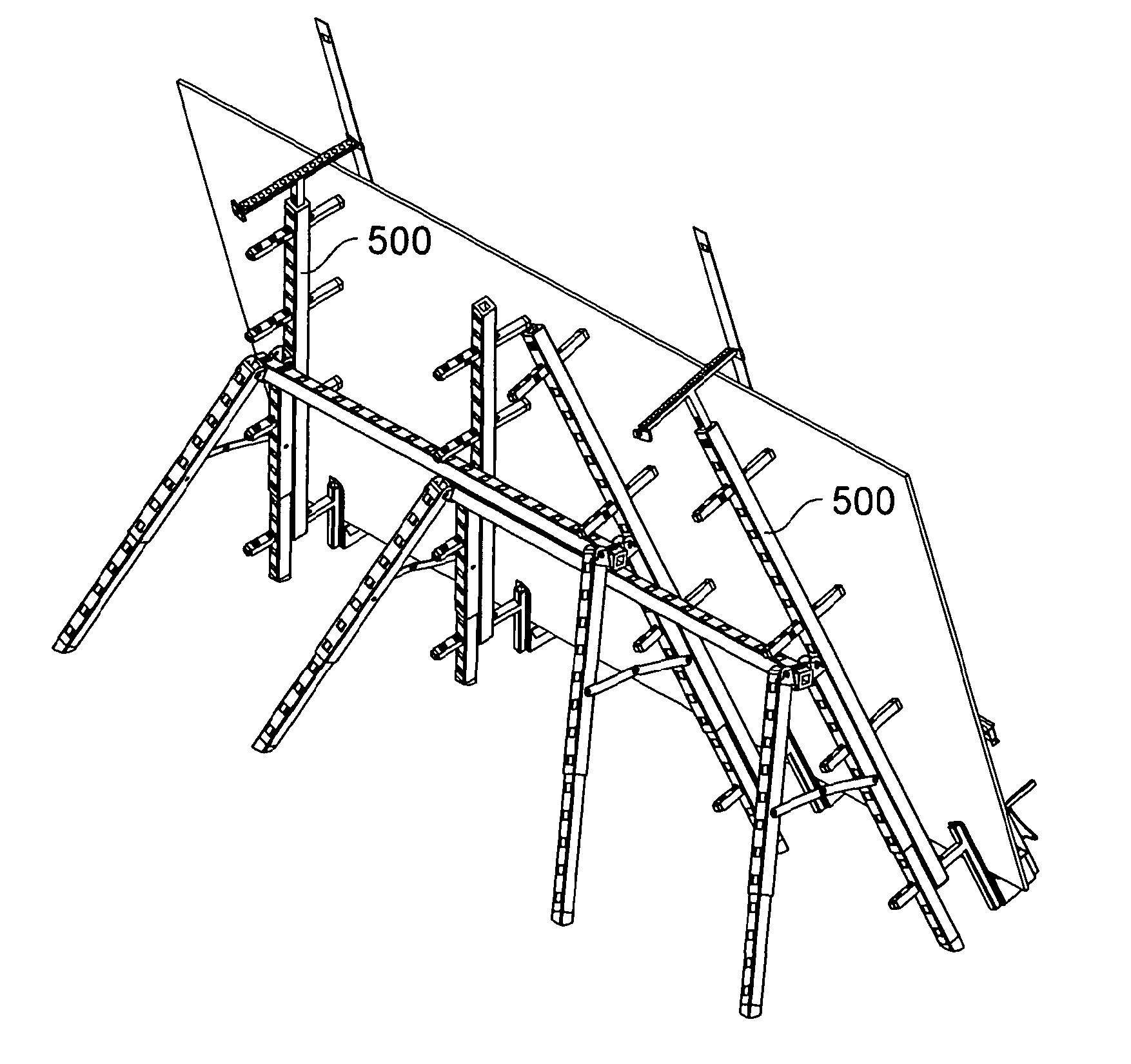
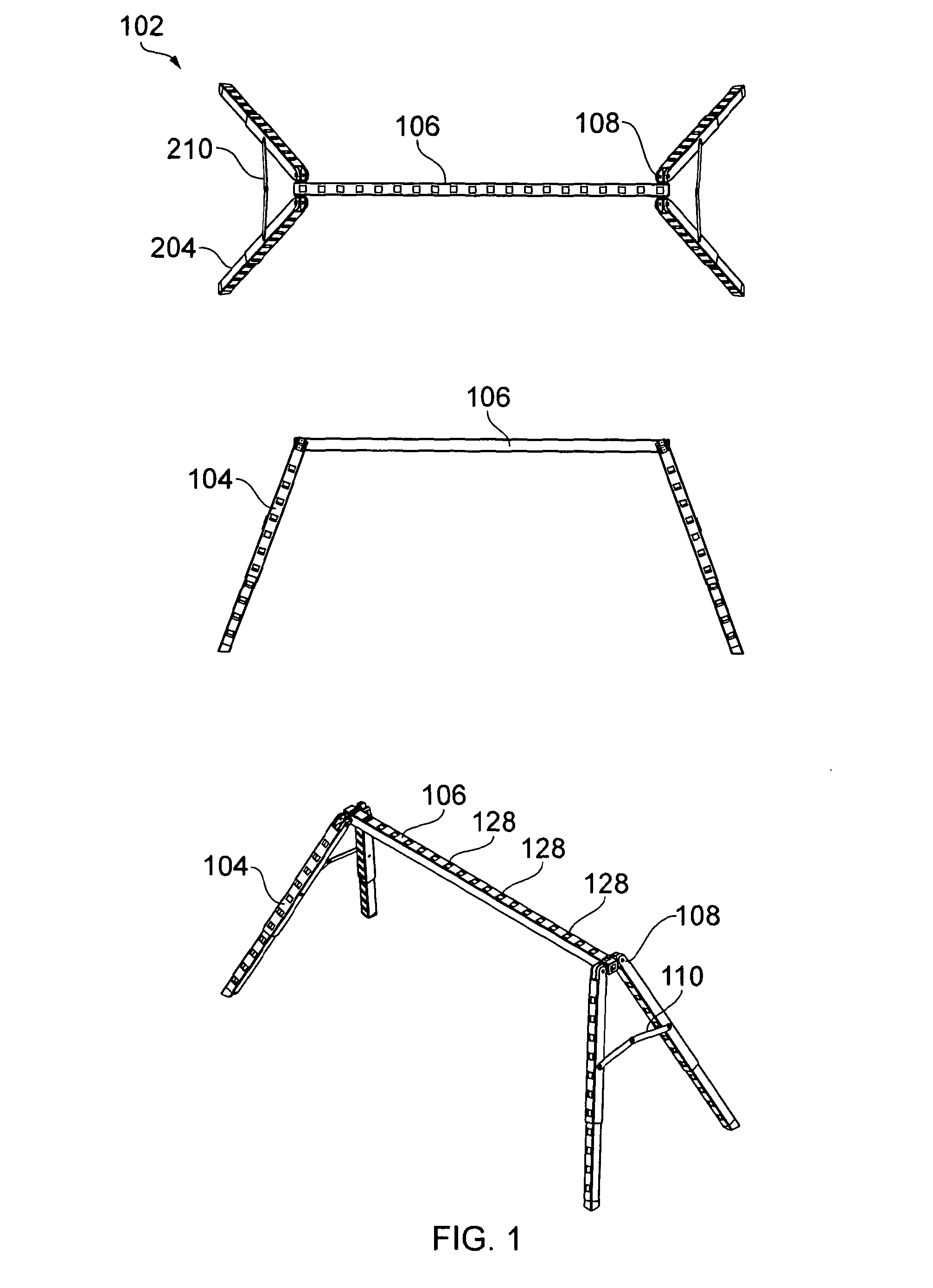
[0072]This is a configurable a workbench that includes one or more trestles (102) having legs (104); and a plurality of beams (500). The beams (500) are adapted to be connected to the trestle (102) so as to form a supporting framework for a work piece. Trestles comprise frame portions that have cross pieces 106 and legs (104) that are optionally removable from the cross piece (106) and foldable as explained in greater detail below. In use the legs (104) are operable to define an A-frame.

[0073]The work piece, which may be a sheet of plywood, glass or wood is a generally larger item of material as used in the building and construction trades, for example door, sheet material, length of pipe or length of timber.

[0074]Typical dimensions of such objects are in the range of about 0.8 m-1.2 m wide to 1.5 m-3.0 m in length.

[0075]Referring now to FIG. 1, which shows s...


PUM


Abstract

The workbench includes one or more trestle units (102) having pairs of legs (104) joined to each end of a cross-piece (106) by a hinge unit (108) which allows the legs to fold flat against each other and against the cross-piece of the trestle for storage. The hinge has a stop which allows the legs to be positioned away from each other and away from the crosspiece of the trestle to form a stable trestle unit. The workbench further includes a plurality of beams (500), wherein said beams are adapted to be connected to at least one trestle so as to form a supporting framework for a work piece. A folding brace (110) between pairs of legs further stabilises the trestle. The beams and trestles have holes (126) in their ends, and the beams and the trestles have regularly spaced holes (128) in them. Pegs can be inserted into and through the holes, and they have locking parts on them, allowing them to lock onto the trestle or beam. Pegs can have two latches for attachment to different beams or trestles. Trestles and beams may be thus interconnected to form a supporting framework.

Description

FIELD OF INVENTION[0001]This invention relates to a workbench, more particularly, but not exclusively the invention relates to a foldable workbench having a plurality of interconnecting beams for supporting a piece of work.BACKGROUND OF THE INVENTION[0002]Workbenches are well known. An example of a very well known and highly commercially successful workbench has been sold for many years by ‘Black & Decker’ under the Registered Trade Mark Workmate®. The workbench has folds to a relatively smaller volume for stowage. However, when professional builders, carpenters and craftsmen needed to support larger items, particularly larger wooden items, such as bookcases, window frames, doors and gates, often two or more such workbenches had to be used in combination, sometimes together with other equipment.[0003]These additional workbenches, and ancillary equipment, added to cost as well as posed problems when cutting or sawing large work pieces, because, for example if a large door or sheet of...

Claims


Application Information

Patent Timeline
Patent Type & Authority Applications(United States)
IPC IPC(8): B25H1/04B25H1/10B25H1/14B25H1/06
CPCB25H1/04B25H1/06B25H1/18B25H1/16B25H1/10
Inventor BOYD, MARK LOCKYER
Owner MB INNOVATIONS LTD
Why Eureka
Try Eureka