Translucent Digital Display System

a digital display system and transparent technology, applied in the field of digital display systems, can solve the problems of obstructing the product or any object behind, limiting the effective use of digital signage in retail sites and out-of-home environments, and the way in which the lcd panels are used,

Active Publication Date: 2013-03-14
STRATACACHE
View PDF13 Cites 101 Cited by
  • Summary
  • Abstract
  • Description
  • Claims
  • Application Information

AI Technical Summary

Benefits of technology

[0009]Also disclosed is a digital display system comprising, in combination, a transparent outer protective panel, a transparent inner protective panel, and a translucent digital video display located between the outer and inner protective panels, and a light guide including a glass panel secured to the translucent video display. The glass panel includes micro-particles therein for reflecting light. A light source is adjacent an edge of the glass panel to provide light within the glass panel that strikes the micro-particles and is reflected out through the outer protective panel. A media player is operably connected to the translucent digital video display so that full-motion videos displayed on the translucent digital video display are viewed through the outer protective panel and items located behind the inner protective panel can be viewed through the translucent digital video display.
[0010]Also disclosed is a digital display system comprising, in combination, a transparent outer protective panel, a transparent inner protective panel, a translucent LCD video display located between the outer and inner protective panels, and a light guide including a glass panel is adhered to the translucent LCD video display. The glass panel includes micro-particles therein for reflecting light. At least one LED adjacent is provided to provide light within the glass panel that strikes the micro-particles and is reflected out through the outer protective panel to provide visibly uniform illumination through the outer protective panel at the LCD video display. A media player operably connected to the translucent LCD video display so that high definition, color, full-motion videos displayed on the translucent LCD video display are viewed through the outer protective panel and items located behind the inner protective panel can be viewed through the translucent LCD video display. A frame encircles peripheries of the outer and inner protective panels and the translucent LCD video display and the media player are sealed within the frame and the outer and inner protective panels.
[0011]From the foregoing disclosure and the following more detailed description of various preferred embodiments it will be apparent to those skilled in the art that the present invention provides a significant advance in the technology and art of digital display systems. Particularly significant in this regard is the potential the invention affords for systems and methods that focus consumer attention in a desired manner without obstructing the customer's line of site in a cost effective manner. Additional features and advantages of various preferred embodiments will be better understood in view of the detailed description provided below.

Problems solved by technology

This methodology has worked well, however by the very nature of LCD panels and their associated hardware, the use of digital signage in retail sites and out-of-home environments is limited by the way in which the LCD panels function.
Primarily, LCD panels are designed as a visual display technology which presents a message to the consumer, but obstructs the product or any object behind the LCD panel because the LCD panel is opaque.
Because traditional LCD panels obstruct the view of any product behind them and cause “line of site” challenges within the retail environment, they are limited in their effective use.

Method used


Image

  • Translucent Digital Display System
  • Translucent Digital Display System
  • Translucent Digital Display System

Examples


Embodiment Construction

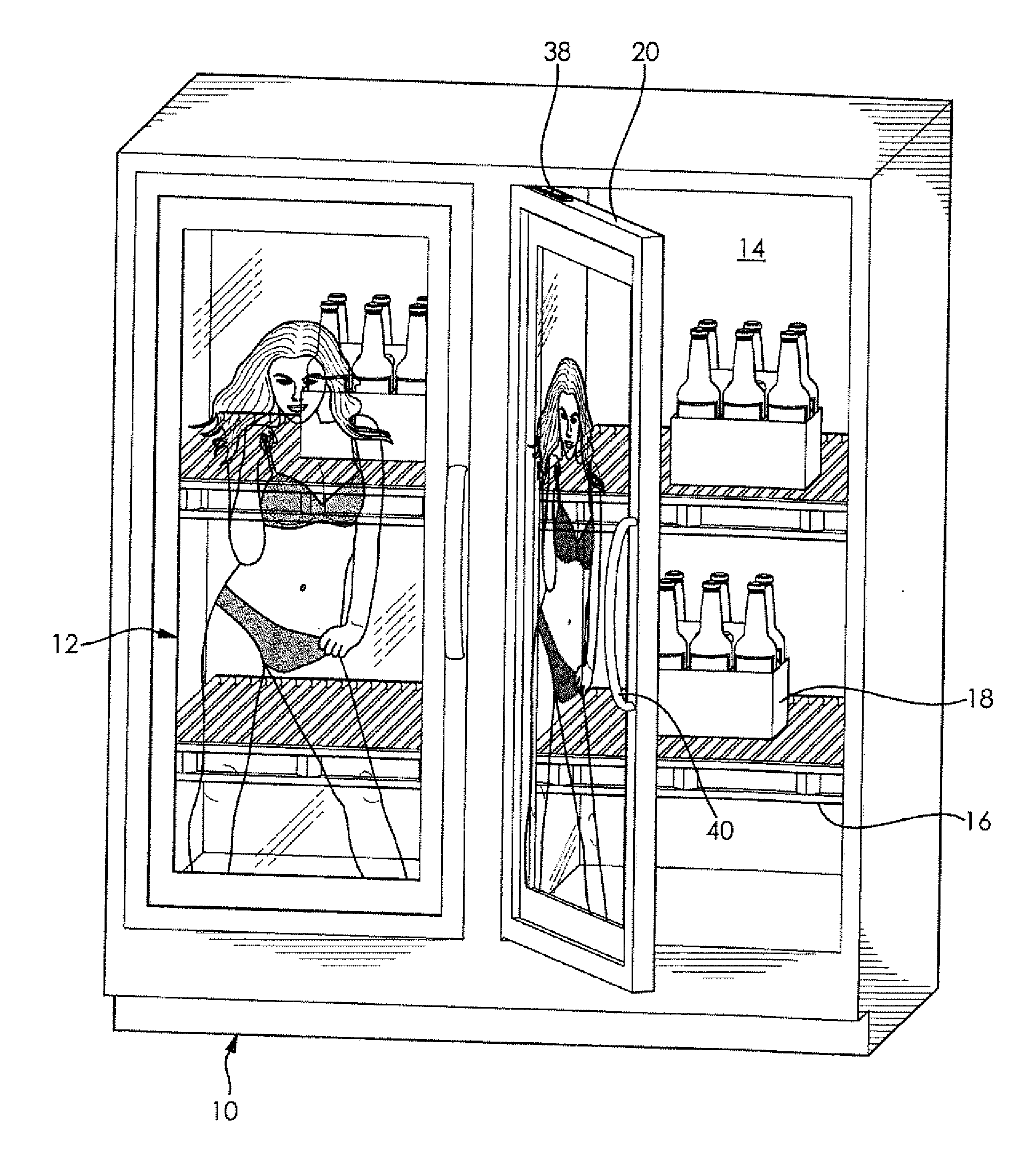
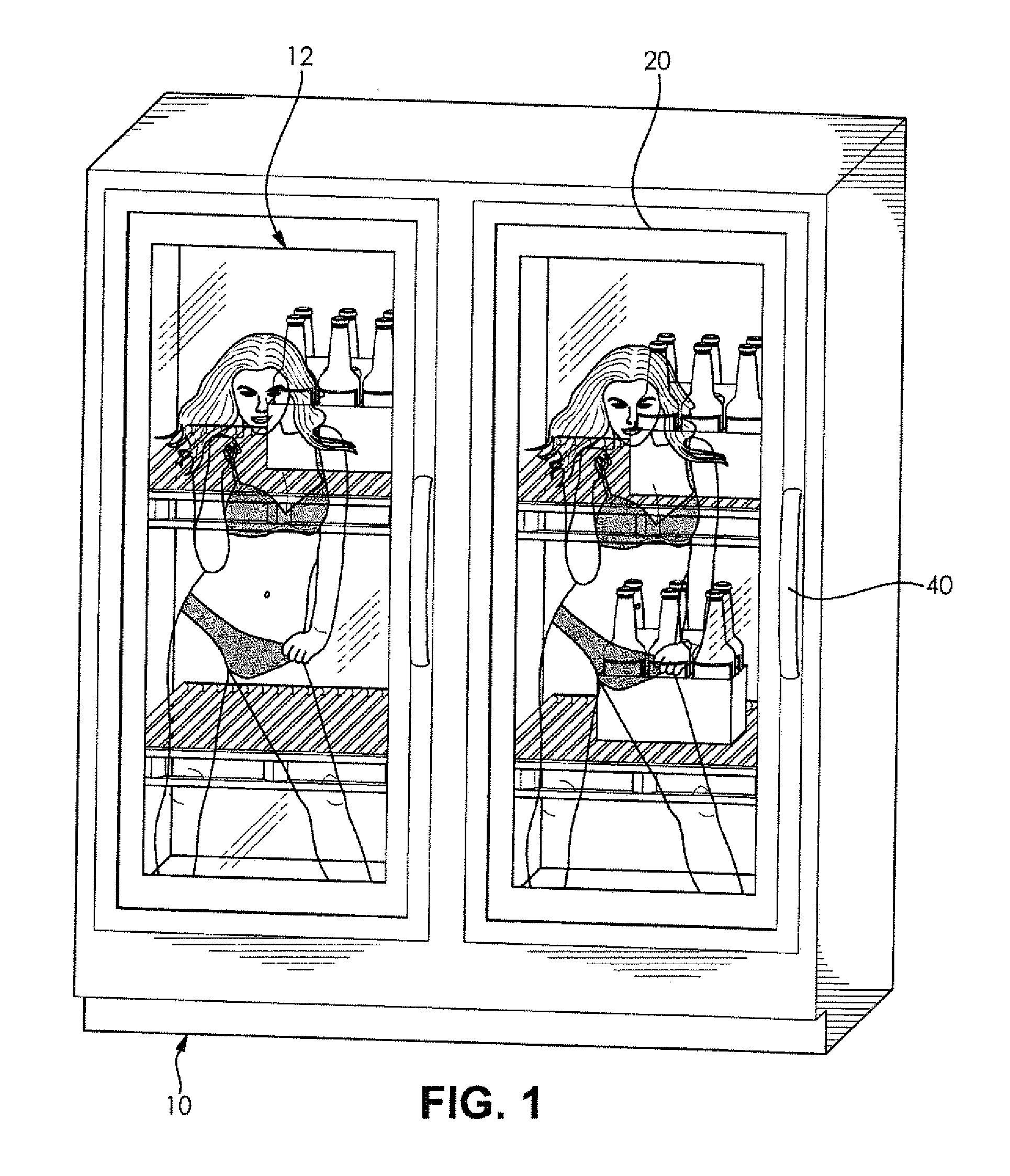
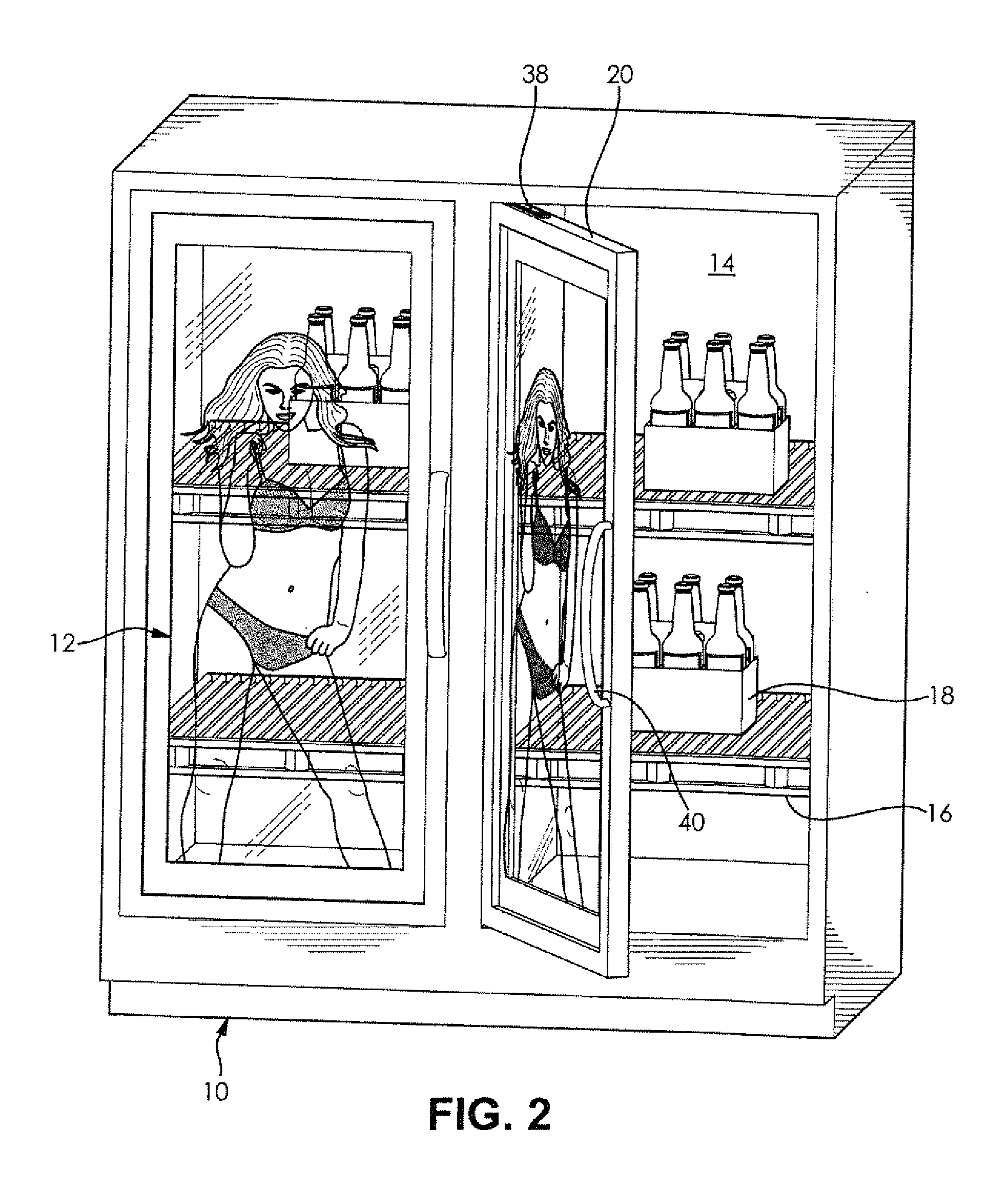
[0023]It will be apparent to those skilled in the art, that is, to those who have knowledge or experience in this area of technology, that many uses and design variations are possible for the improved digital display systems and methods disclosed herein. The following detailed discussion of various alternative and preferred embodiments will illustrate the general principles of the invention with regard to the specific application of glass displays and architectural glass. Other embodiments suitable for other applications will be apparent to those skilled in the art given the benefit of this disclosure.

[0024]FIGS. 1 and 2 illustrate a double glass-door upright cooler or chiller 10 having translucent digital display systems 12 according to the present invention. The illustrated cooler 10 has a interior space 14 which is cooled by a suitable refrigeration system to keep product displayed therein at a desired temperature. The illustrated interior space 14 is provided with a plurality of...


PUM


Abstract

A digital display system includes a transparent outer protective panel, a transparent inner protective panel, and a translucent digital video display located between the outer and inner protective panels. An integrated media player is operably connected to the translucent digital video display so that full-motion videos displayed on the translucent digital video display are viewed through the outer protective panel and items can be viewed through the translucent digital video display. The digital display system can be incorporated into any environment where a product is located behind a glass enclosure such as freezers, coolers, security glass, jewelry cases, liquor cases, cosmetic cases, and the like. In retail environments, the digital display systems can also be incorporated into entry doors, windows, drive-thru windows, teller windows, and any other location where there is traditionally glass and you want to focus consumer attention obstructing the customer's line of site.

Description

CROSS-REFERENCE TO RELATED APPLICATIONS[0001]This application claims the priority of U.S. Provisional Patent Application No. 61 / 448,455 filed on Mar. 2, 2011, the disclosure of which is expressly incorporated herein in its entirety by reference.STATEMENT REGARDING FEDERALLY SPONSORED RESEARCH[0002]Not ApplicablePARTIES TO A JOINT RESEARCH AGREEMENT[0003]Not ApplicableREFERENCE TO APPENDIX[0004]Not ApplicableFIELD OF THE INVENTION[0005]The field of the present invention generally relates to digital display systems and, more particularly, to translucent digital display systems having glass packaging.BACKGROUND OF THE INVENTION[0006]In consumer retail environments today, there is a desire on the part of brands and retailers to place messages in front of the consumer at their “point of purchase” or “point of product selection”. Historically in retail, banking, quick service restaurants (QSR), hospitality, etc. (and out-of-home advertising in general) this messaging has been paper based ...

Claims


Application Information

Patent Timeline
Patent Type & Authority Applications(United States)
IPC IPC(8): G09G5/00
CPCG09F9/33G09F9/35A47F3/043G02F1/133615G09F2023/0033G02B6/0041G02B6/0095G09F23/065A47F3/001G07F9/023G02F1/133342G02B6/0093G02F1/133308G02F2203/02H04N5/64
Inventor RIEGEL, CHRISTOPHER K.
Owner STRATACACHE
Why Eureka
Try Eureka