Image forming apparatus and vehicle on which the image forming apparatus is mounted

Active Publication Date: 2013-03-14
RICOH KK
View PDF5 Cites 67 Cited by
  • Summary
  • Abstract
  • Description
  • Claims
  • Application Information

AI Technical Summary

Benefits of technology

[0009]The present invention may provide an image forming apparatus and a vehicle on which an image forming apparatus is mou

Problems solved by technology

However, by pursing size-reduction of the image forming apparatus, there are problems such as being unable to attain brightness or being unable to provide a la

Method used


Image

  • Image forming apparatus and vehicle on which the image forming apparatus is mounted
  • Image forming apparatus and vehicle on which the image forming apparatus is mounted
  • Image forming apparatus and vehicle on which the image forming apparatus is mounted

Examples


first embodiment

Modified Example of First Embodiment

[0074]In the modified example of the first embodiment, the arrangement of optical elements in an optical scanning device is different from that of the optical scanning device 10 of the first embodiment. In the modified example of the first embodiment, like components are denoted with like reference numerals as those of the first embodiment and are not further described.

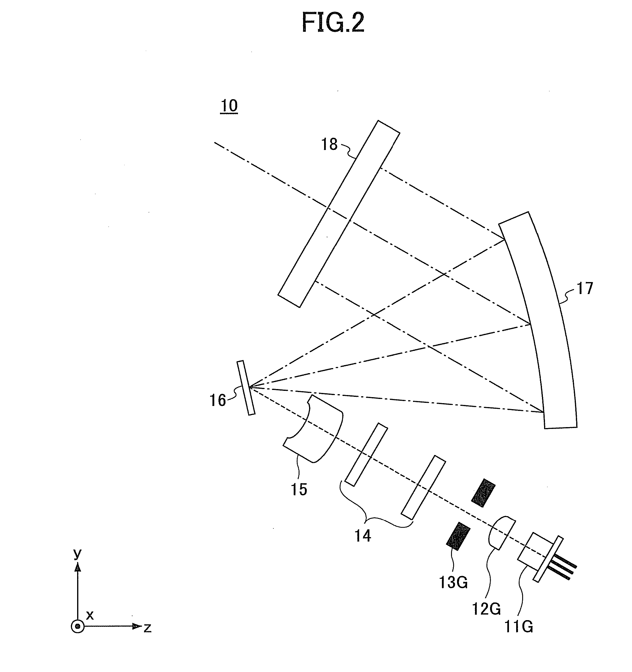
[0075]FIG. 8 is a schematic diagram illustrating an optical path of an optical scanning device 10A according to the modified example of the first embodiment. More specifically, FIG. 8 illustrates the optical path of the optical scanning device 10A viewed from the same direction as FIG. 3. Similar to FIG. 3, the optical deflector 16, the concave mirror 17, and the target scanning surface 18 are not illustrated in FIG. 8 for the sake of convenience. In the optical scanning device 10A, the arrangement of the optical deflector 16, the concave mirror 17, and the target scanning surface 1...

first example

[0080]FIG. 9 is a schematic diagram illustrating an optical system according to the first example. As illustrated in FIG. 9, a convex mirror is used as the first mirror 21, a concave mirror is used as the second mirror 22, and a half mirror having a flat reflection surface is used as the half mirror 23 in the first example.

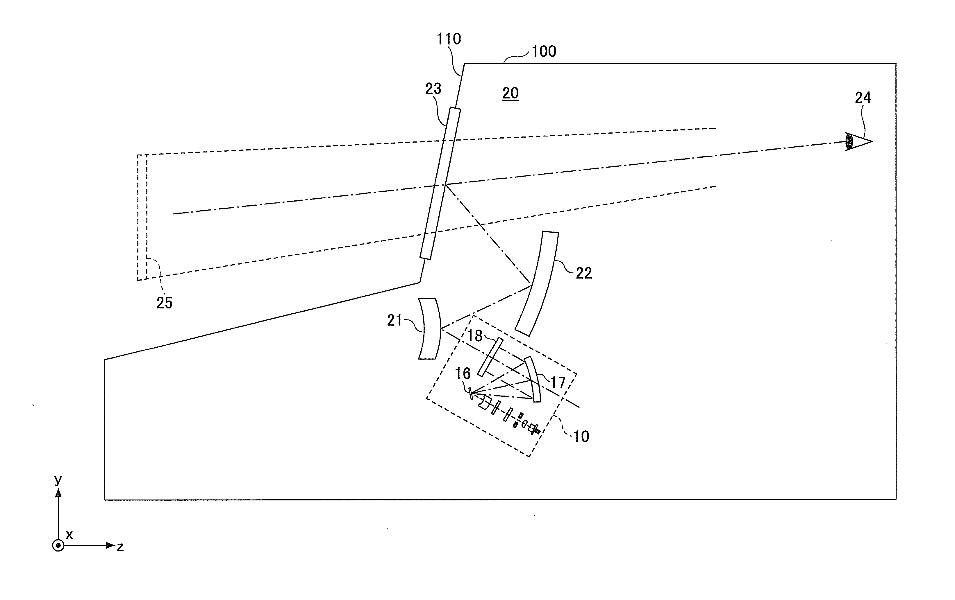
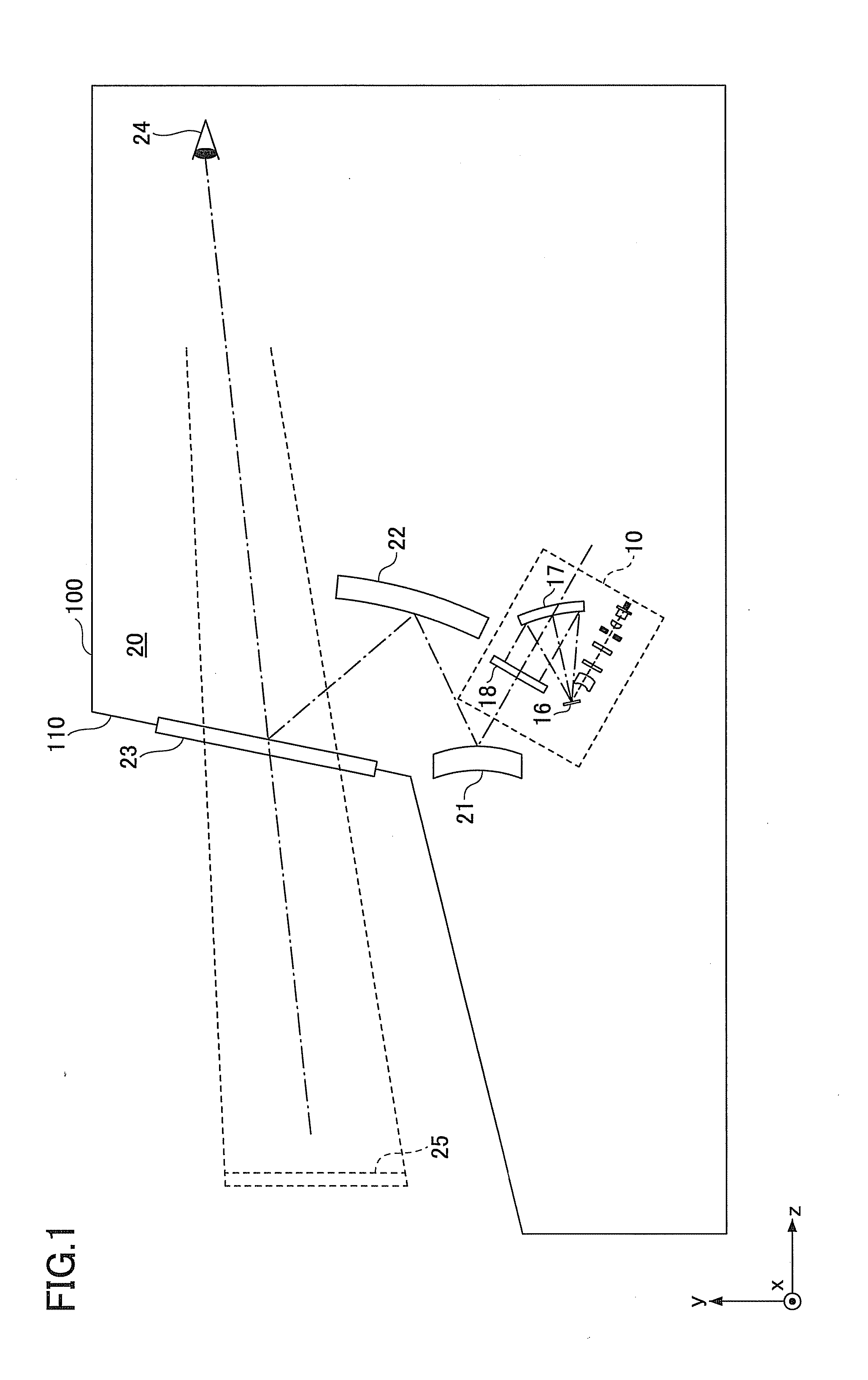
[0081]In the first example, although the light beams transmitted from the target scanning surface 18 are incident on the first mirror (convex mirror) 21, the first mirror 21 increases the radiation angle of the incident light beams. Thereby, the length of the optical paths in the image forming apparatus can be shortened.

[0082]In order to allow a driver of the vehicle 100 to view the enlarged virtual image 25, a final power surface is to have enough power to converge multiple light beams. Because the half mirror 23 of the first example has a flat surface, a concave mirror is to be used as the second mirror 22, so that the entire projection optical system can have a...

second example

[0085]FIG. 10 is a schematic diagram illustrating an optical system according to the second example. As illustrated in FIG. 10, a convex mirror is used as the first mirror 21, a flat mirror is used as the second mirror 22, and a half mirror having a concave reflection surface is used as the half mirror in the second example. In the second example, although the reflection surface of the half mirror 23 is a concave surface, a surface of the half mirror 23 opposite to the reflection surface is substantially parallel to the reflection surface. In other words, the thickness of the half mirror 23 is substantially uniform.

[0086]In the second example, the convex surface of the first mirror 21 is an anamorphic surface in which a curvature of a predetermined direction is different from a curvature of a direction orthogonal to the predetermined direction. By using an anamorphic surface as the reflection surface of the first mirror 21, the curved shaped of the convex surface of the first mirror...


PUM

PropertyMeasurementUnit
Shapeaaaaaaaaaa
Transparencyaaaaaaaaaa

Abstract

An image forming apparatus includes an optical scanning device including a light source element configured to radiate a light beam, an optical deflector configured to deflect the light beam two-dimensionally, and a target scanning surface that is transparent and having a two-dimensional image formed thereon by the light beam deflected from the optical deflector, and a projection optical system including a convex mirror and configured to enlarge and project the two-dimensional image on a target projection surface. The target projection surface includes a reflection surface of a half mirror. The half mirror is positioned outside of the image forming apparatus and configured to transmit a part of a light incident on the half mirror and reflect another part of the light incident on the half mirror.

Description

BACKGROUND OF THE INVENTION[0001]1. Field of the Invention[0002]The present invention relates to an image forming apparatus and a vehicle on which the image forming apparatus is mounted; for example, an image forming apparatus including an optical scanning device for forming a two-dimensional image by scanning a light beam from an optical element, and a vehicle on which such image forming apparatus is mounted.[0003]2. Description of the Related Art[0004]In recent years, there has been widely proposed an optical scanning device that forms a two-dimensional image by irradiating multicolor light beams to a mirror that can scan in two-dimensional directions. Particularly, with an optical scanning device using a semiconductor laser as a light source, high light-use efficiency can be attained owing to the high directivity of a light beam irradiated from the semiconductor laser. Further, with the optical scanning device using a semiconductor laser, strong light can be generated inside the ...

Claims


Application Information

Patent Timeline
IPC IPC(8): G06K15/02
CPCG02B5/02G02B26/0858G02B26/101G02B26/105G02B27/0966G02B27/0101G03B33/12B23K26/0643B23K26/0648G02B19/0057G02B19/0028G03B21/28G03B33/06B23K26/0639B23K26/064G02B5/0257G02B5/0278
Inventor SAISHO, KENICHIROHSATOH, HIROYUKI
Owner RICOH KK
Why Eureka
Try Eureka