Electrical connection system

Active Publication Date: 2013-03-14
ROSENBERGER HOCHFREQUENZTECHNIK GMBH & CO KG
View PDF40 Cites 18 Cited by
  • Summary
  • Abstract
  • Description
  • Claims
  • Application Information

AI Technical Summary

Benefits of technology

This patent text describes a solution for making a connection between a plug and a socket using a magnetic device. The solution addresses the issue of interference caused by magnetic devices in sensitive areas, such as medical facilities. The plug no longer has a magnet and does not produce a magnetic field that could affect medical equipment. Additionally, the patent describes the use of a ball joint, rotating joint, or hinge in the plug to prevent accidental disconnection of the plug from the socket. This design allows for force to be transmitted to the plug only when it reaches its maximum point of load, reducing the risk of disconnection. Overall, this solution provides the benefits of a magnetic connection between a plug and socket while addressing potential interference and accidental disconnection.

Problems solved by technology

However, applications are known, in particular in medical care facilities and in hospitals, in which the use of magnets is impossible, since situations can arise there in which the magnets interfere with medical units which are important to life, for example heart pacemakers implanted in the patients.
In this case, it is particularly problematic if, for example, a plug becomes detached from a socket as a result of an accidental pulling or bending load, and falls onto the chest of a patient, thus having a negative influence on an implanted heart pacemaker.

Method used


Image

  • Electrical connection system
  • Electrical connection system
  • Electrical connection system

Examples


Embodiment Construction

[0044]In principle, electrical connection systems are already known from the general prior art, in which context reference is made, for example, to DE 20 2006 020 263 U1. Electrical connection systems are particularly suitable for transmission of signals, data or current. Only those features which are essential to the invention will be described in more detail in the following text.

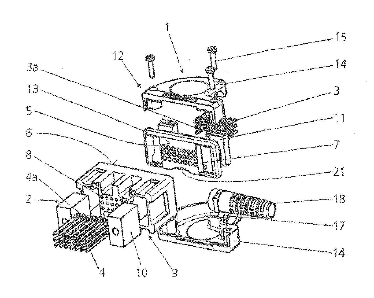
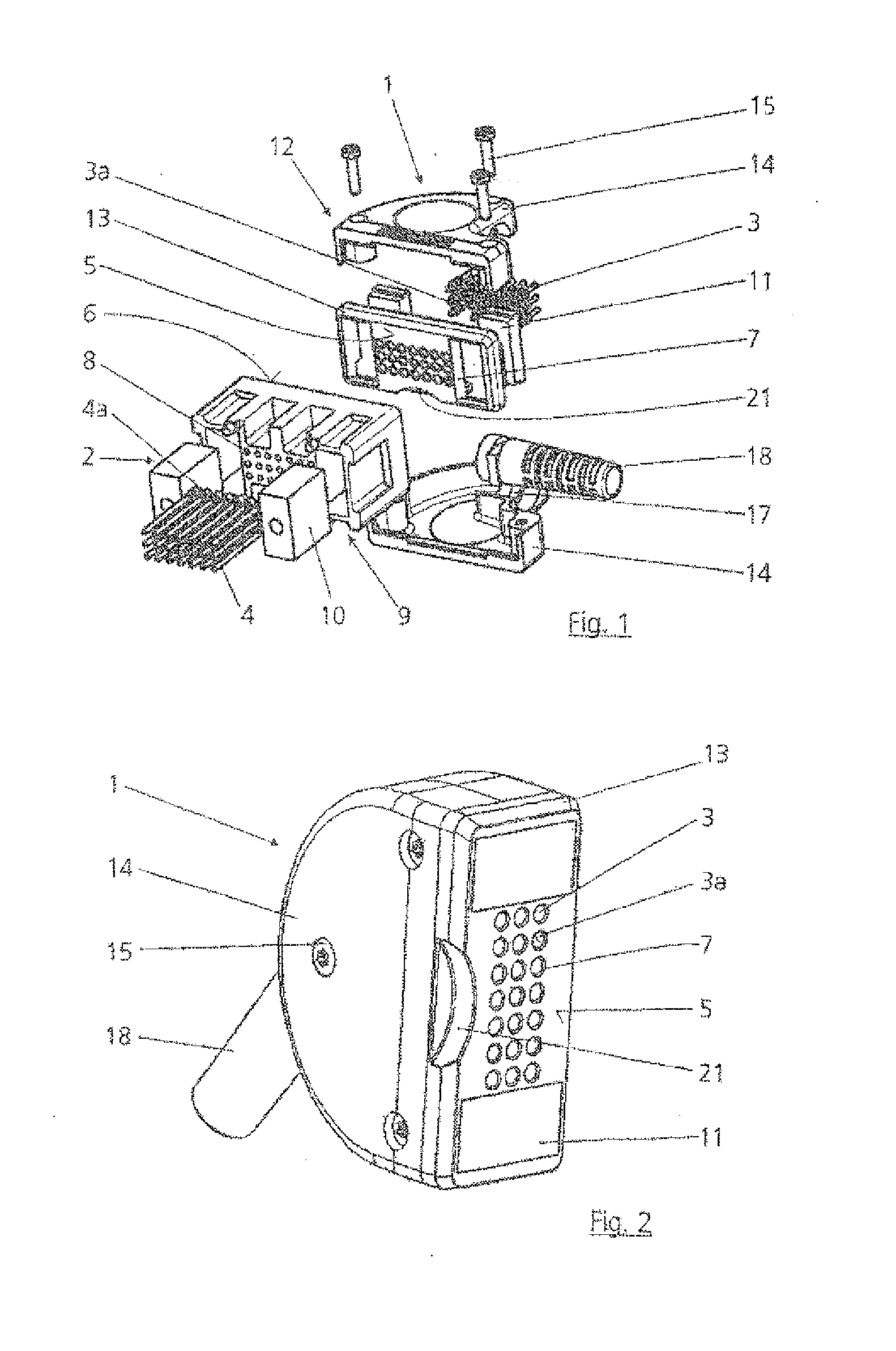
[0045]FIG. 1 shows an electrical connection system having a plug 1 and a socket 2. The plug 1 in this case has a plurality of contact elements 3, and the socket 2 has a corresponding number of mating contact elements 4. The contact elements 3 are inserted in the plug 1 such that their contact surfaces 3a are arranged essentially on a plane with a front face 5, facing the socket 2, of the plug 1. The mating contact elements 4 are inserted analogously in the socket 2 such that their mating contact surfaces 4a are arranged essentially flush on a plane with a front face 6, facing the plug 1, of the socket 2.

[...


PUM


Abstract

An electrical connection system includes a plug having contact elements, and a socket having mating contact elements. The plug can be connected magnetically to the socket by means of a magnet device for transmitting signals or current. The magnet device has at least one connection pair, which comprises a magnet and a connecting element, which can be attracted by the magnet, but itself is not in the form of a permanent magnet, wherein respectively the magnet of a connection pair is arranged in the socket, and the connecting element which is not in the form of a permanent magnet is arranged in the plug.

Description

CROSS REFERENCE TO RELATED APPLICATIONS[0001]This applications claims priority under 35 U.S.C. Sections 119(a)-(d), 120, 363, and 365 to International Patent Application No. PCT / EP2011 / 057024, filed May 3, 2011 which designated the United States and at least one other country in addition to the United States and claimed priority to German Application No. 10 2010 028 791.1, filed May 10, 2010. Both PCT / EP2011 / 057024 and German Application No. 10 2010 028 791.1 are expressly incorporated by reference herein in their entirety to form a part of the present disclosure.FIELD OF THE INVENTION[0002]The invention relates to an electrical connection system having a plug which has contact elements, and having a socket which has mating contact elements, according to the precharacterizing clause of Claim 1. The invention furthermore relates to a plug and a socket for an electrical connection system according to Claims 10 and 12. The invention additionally relates to an electronic component or an...

Claims


Application Information

Patent Timeline
IPC IPC(8): H01R11/30
CPCH01R13/562H01R13/5841H01R2201/12H01R13/6205F42B4/20H01R13/22H01R13/64H01R2107/00H01R13/631
Inventor SCHICHL, MARKUSMICHELMANN, FOLKE
Owner ROSENBERGER HOCHFREQUENZTECHNIK GMBH & CO KG
Why Eureka
Try Eureka