Hydraulic control unit for use in valve timing control apparatus and controller for hydraulic control unit

a technology of hydraulic control unit and valve timing control, which is applied in the direction of valve details, valve arrangements, machines/engines, etc., can solve the problems of long release time and undesirable device time delay, and achieve the effect of less time delay and rapid unlocking of the lock mechanism

Inactive Publication Date: 2013-03-21
HITACHI AUTOMOTIVE SYST LTD
View PDF0 Cites 13 Cited by
  • Summary
  • Abstract
  • Description
  • Claims
  • Application Information

AI Technical Summary

Benefits of technology

[0005]Therefore, it would be desirable to rapidly unlocking the lock mechanism with a less time delay, while using an exclusive electrical control system, only used for the lock mechanism.
[0006]It is, therefore, in view of the previously-described disadvantages of the prior art, an object of the invention to provide a hydraulic control unit for use in a valve timing control apparatus and a controller for the hydraulic control unit, capable of rapidly unlocking a lock mechanism (a position-hold mechanism) configured to lock or hold a vane rotor at an intermediate position between a maximum phase-advance position and a maximum phase-retard position.

Problems solved by technology

That is, this device requires an undesirable time delay (a long release time) during a transition from the locked state to the unlocked state.

Method used


Image

  • Hydraulic control unit for use in valve timing control apparatus and controller for hydraulic control unit
  • Hydraulic control unit for use in valve timing control apparatus and controller for hydraulic control unit
  • Hydraulic control unit for use in valve timing control apparatus and controller for hydraulic control unit

Examples


second embodiment

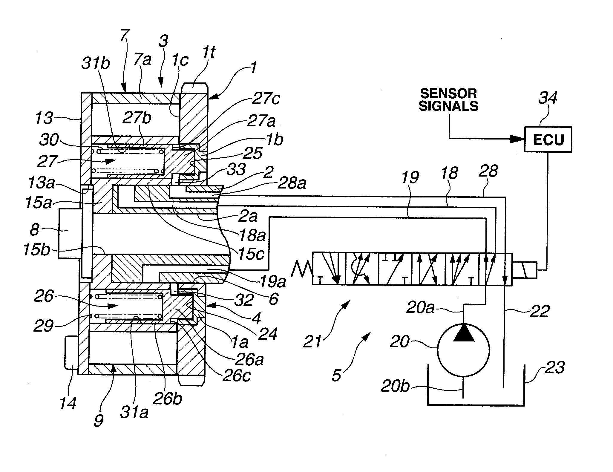
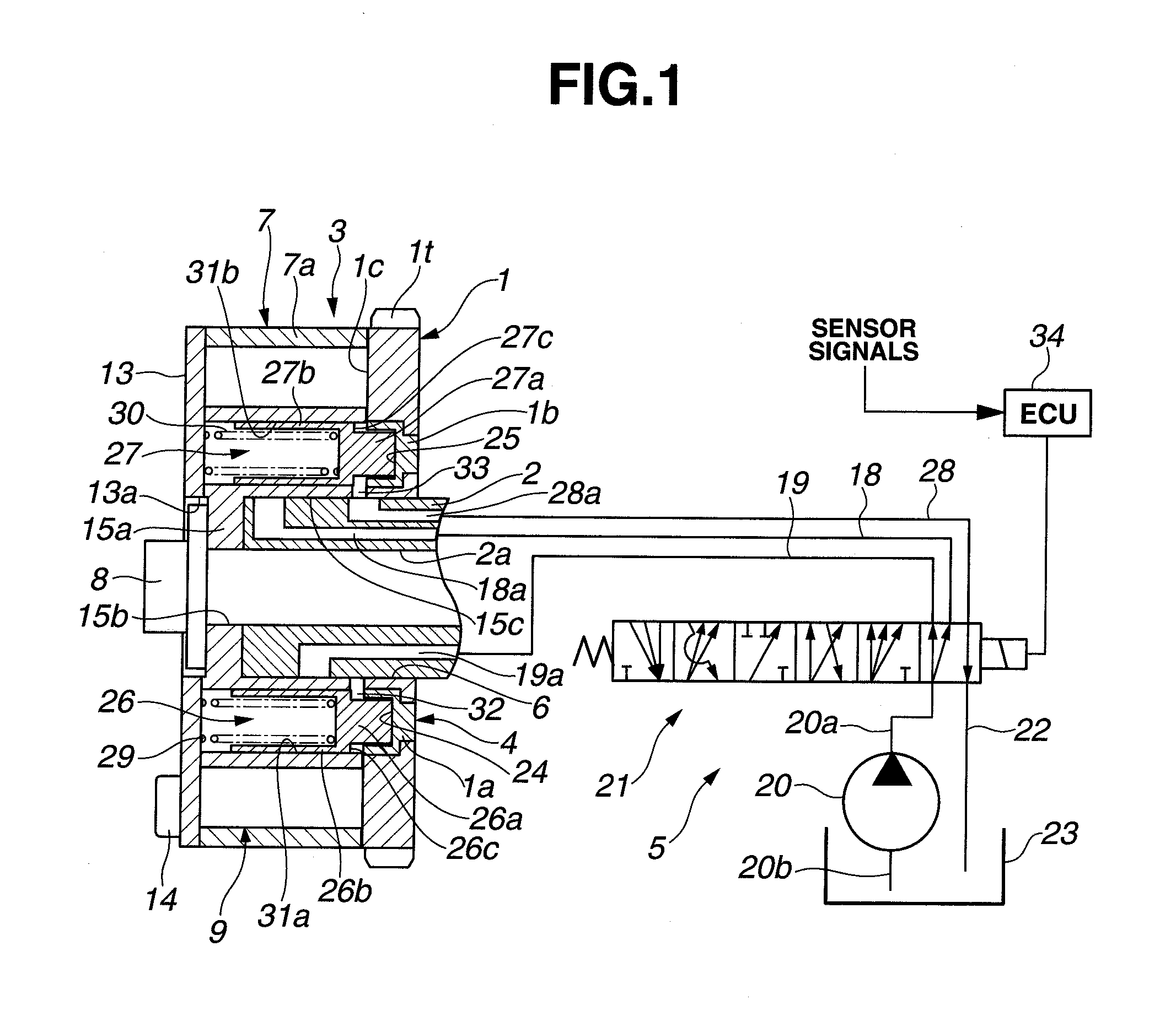
[0147]Referring now to FIGS. 20A-20B, there are shown the longitudinal cross sections of the electromagnetic directional control valve of the second embodiment. FIG. 20B shows the longitudinal cross section of the directional control valve of the second embodiment at an angular position rotated 90 degrees from the angular position corresponding to the cross section of FIG. 20A. As appreciated from comparison between the longitudinal cross section of FIG. 11 (the first embodiment) and the longitudinal cross section of FIG. 20A (the second embodiment), the control valves of the first and second embodiments somewhat differ from each other, in that, in the second embodiment, passage grooves are formed in the outer peripheral surface of valve body 51 (the valve housing) instead of forming a passage hole 60 in the valve spool 52.

[0148]That is, in the same manner as the first embodiment, in the second embodiment, as seen in FIG. 20A, valve body 51 has first and second introduction ports 55...

third embodiment

[0161]Referring now to FIG. 27, there is shown the hydraulic control unit of the third embodiment employing two different electromagnetic directional control valves 81-82 provided for independently controlling the phase-change mechanism 3 and the position-hold mechanism 4. The third embodiment somewhat differs from the first and second embodiments, in that, in the third embodiment, a first electromagnetic directional control valve 81 for phase-change mechanism 3 and a second electromagnetic directional control valve 82 for position-hold mechanism 4 (the lock mechanism) are provided separately from each other, instead of using a single electromagnetic directional control valve. First and second electromagnetic directional control valves 81-82 are constructed or formed as a more efficient and economical, compact directional control valve unit, which can be easily installed on the vehicle. In explaining the third embodiment, for the purpose of simplification of the disclosure, the same...


PUM


Abstract

A hydraulic control unit is configured to switch among a first state where a discharge passage of a pump driven by an internal combustion engine communicates with both a phase-advance passage and a lock passage and simultaneously a phase-retard passage communicates with a drain passage, a second state where the discharge passage communicates with both the phase-retard passage and the lock passage and simultaneously the phase-advance passage communicates with the drain passage, and a third state where the phase-advance passage, the phase-retard passage, and the lock passage all communicate with the discharge passage. The hydraulic control unit is further switchable to a fourth state where the discharge passage communicates with both the phase-advance passage and the phase-retard passage and simultaneously the lock passage communicates with the drain passage.

Description

TECHNICAL FIELD[0001]The present invention relates to a hydraulic control unit for use in a valve timing control apparatus configured to variably control valve timing of an engine valve, such as an intake valve and / or an exhaust valve, depending on an engine operating condition, and specifically to a controller for the hydraulic control unit.BACKGROUND ART[0002]In recent years, there have been proposed and developed various hydraulically-operated vane rotor equipped variable valve timing control devices, capable of locking a vane rotor at an intermediate position between a maximum phase-advance position and a maximum phase-retard position by means of a lock mechanism during a starting period of an internal combustion engine. To unlock the lock mechanism, working fluid (hydraulic oil) in either a phase-advance chamber or a phase-retard chamber is used. When unlocking the lock mechanism by the use of working fluid (hydraulic oil) in either the phase-advance chamber or the phase-retard...

Claims


Application Information

Patent Timeline
Patent Type & Authority Applications(United States)
IPC IPC(8): F01L1/344
CPCF01L1/3442F01L2001/3443F01L2001/34463F01L2001/34466F01L2001/34469F01L2800/00F01L2001/34479F01L2101/00F01L2103/00F01L2250/02F01L2001/34476F01L2301/00F01L2303/00
Inventor TAKADA, YASUHIDE
Owner HITACHI AUTOMOTIVE SYST LTD
Why Eureka
Try Eureka