Suspension apparatus

Inactive Publication Date: 2017-08-24
KYB CORP
View PDF3 Cites 3 Cited by
  • Summary
  • Abstract
  • Description
  • Claims
  • Application Information

AI Technical Summary

Benefits of technology

The patent text discusses the advantages and disadvantages of increasing or decreasing the inner diameter of the cylinder of the damper in a suspension apparatus. The goal of the patent is to provide a solution to improve the damping force characteristics of the suspension apparatus.

Problems solved by technology

However, the sensitivity of the damping force relative to the characteristics of the valve is high, and thus fluctuations in the damping force tend to occur in each article.
Further, the flow rate of the hydraulic oil that passes through the valve is high and the outer diameter of leaf valves that are laminated in the piston also increases, and thus there is a tendency for delays in the closing of the leaf valves to occur during switching of the operation direction from extension to contraction or from contraction to extension, which frequently leads to time delays in generation of the damping force.
In addition, the pressure receiving area is also small, and thus in a damper in which the inner diameter of the cylinder is small, the rise in the damping force tends to be slow.

Method used


Image

  • Suspension apparatus
  • Suspension apparatus
  • Suspension apparatus

Examples


first embodiment

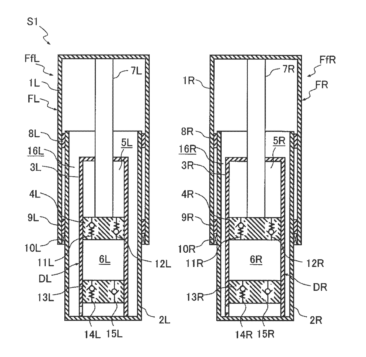
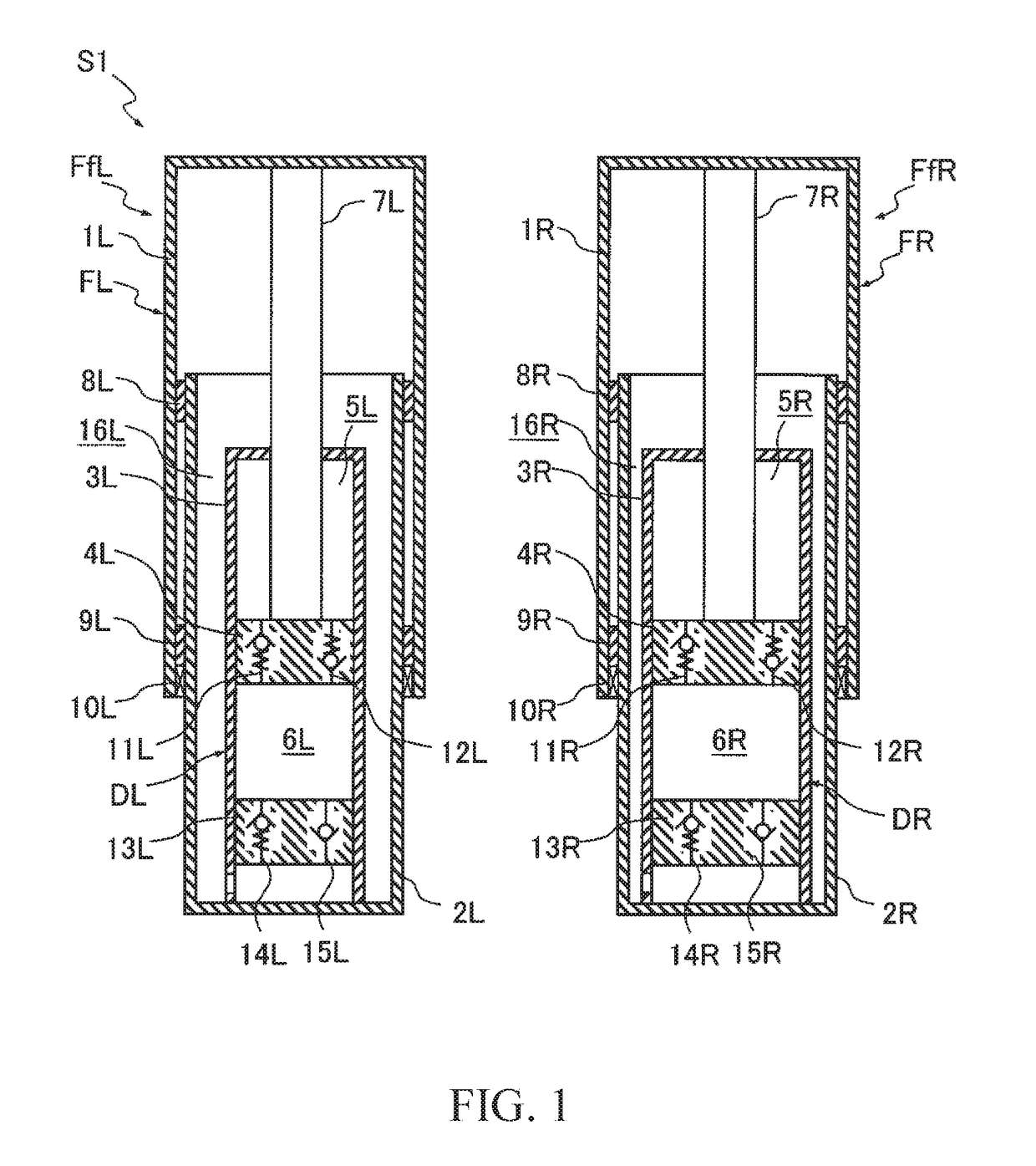
[0018]As shown in FIG. 1, a suspension apparatus S1 according to a first embodiment includes a pair of front forks FfR and FfL. The pair of front forks FfR and FfL are interposed between the vehicle body and the vehicle axle of a saddle-type vehicle (not illustrated), and suspend the vehicle wheel on the vehicle body.

[0019]The front forks FfR, FfL include a fork main bodies FR, FL and a dampers DR, DL accommodated within the fork main bodies FR, FL, respectively. The fork main bodies FR, FL include an outer tubes 1R, 1L, and an inner tubes 2R, 2L slidably inserted into the outer tubes 1R, 1L, respectively. The dampers DR, DL extend / contract in accordance with the extension / contraction of the fork main bodies FR, FL to exert a damping force, respectively.

[0020]Each part of the suspension apparatus S1 will now be explained in detail below. The outer tubes 1R, 1L and the inner tubes 2R, 2L have a cylindrical shape in which one end is closed. In the fork main bodies FR, FL, the inner tu...

second embodiment

[0062]Next, a suspension apparatus S2 of a second embodiment will be explained below. In the suspension apparatus S2 of the second embodiment, as shown in FIG. 4, the structures of the dampers DR and DL differ from those of the suspension apparatus S1 of the first embodiment. Since detailed explanations of those constituent members which are the same in both the suspension apparatus S2 of the second embodiment and the suspension apparatus S1 of the first embodiment would be redundant, in the following, those constituent members which are the same will merely be assigned the same reference numeral and detailed explanations thereof will be omitted.

[0063]With regard to the suspension apparatus S2 of the second embodiment, the following detailed explanations will focus on those portions which differ from the suspension apparatus S1 of the first embodiment. The damper DR does not include the valve case 13R (refer to FIG. 1), and a through hole 23 which constantly allows the contraction-s...


PUM


Abstract

A suspension apparatus includes a pair of dampers configured to extend / contract to exert a damping force, each of the dampers includes a cylinder, a piston slidably inserted into the cylinder and configured to partition the inside of the cylinder into an extension-side chamber and a contraction-side chamber, and a piston rod connected to the piston and movably inserted into the cylinder, and an inner diameter of the cylinder of one of the dampers is different from an inner diameter of the cylinder of the other.

Description

TECHNICAL FIELD[0001]The present invention relates to a suspension apparatus.BACKGROUND ART[0002]A suspension apparatus that supports a steered wheel on the front side of a saddle-type vehicle is conventionally constituted by a pair of front forks. Each front fork includes, for example, a fork main body having an outer tube and an inner tube that is movably inserted into the outer tube, and a damper that is accommodated within the fork main body.[0003]The damper includes the following: a cylinder connected to the inner tube; a piston that is slidably inserted into the cylinder; a piston rod that is movably inserted into the cylinder; an extension-side damping passage, and a contraction-side damping passage. The piston partitions the inside of the cylinder into an extension-side chamber and a contraction-side chamber, and hydraulic oil is filled into the extension-side chamber and the contraction-side chamber. One end of the piston rod is connected to the piston, and the other end is...

Claims


Application Information

Patent Timeline
IPC IPC(8): B62K25/08
CPCB62K25/08B62K2201/08B62K2025/044F16F9/516F16F9/28
Inventor KURITA, NORIHIKO
Owner KYB CORP
Why Eureka
Try Eureka