

Radiant heating device for vehicle
- Summary
- Abstract
- Description
- Claims
- Application Information
AI Technical Summary
Benefits of technology
Problems solved by technology
Method used
Image

Examples
first embodiment
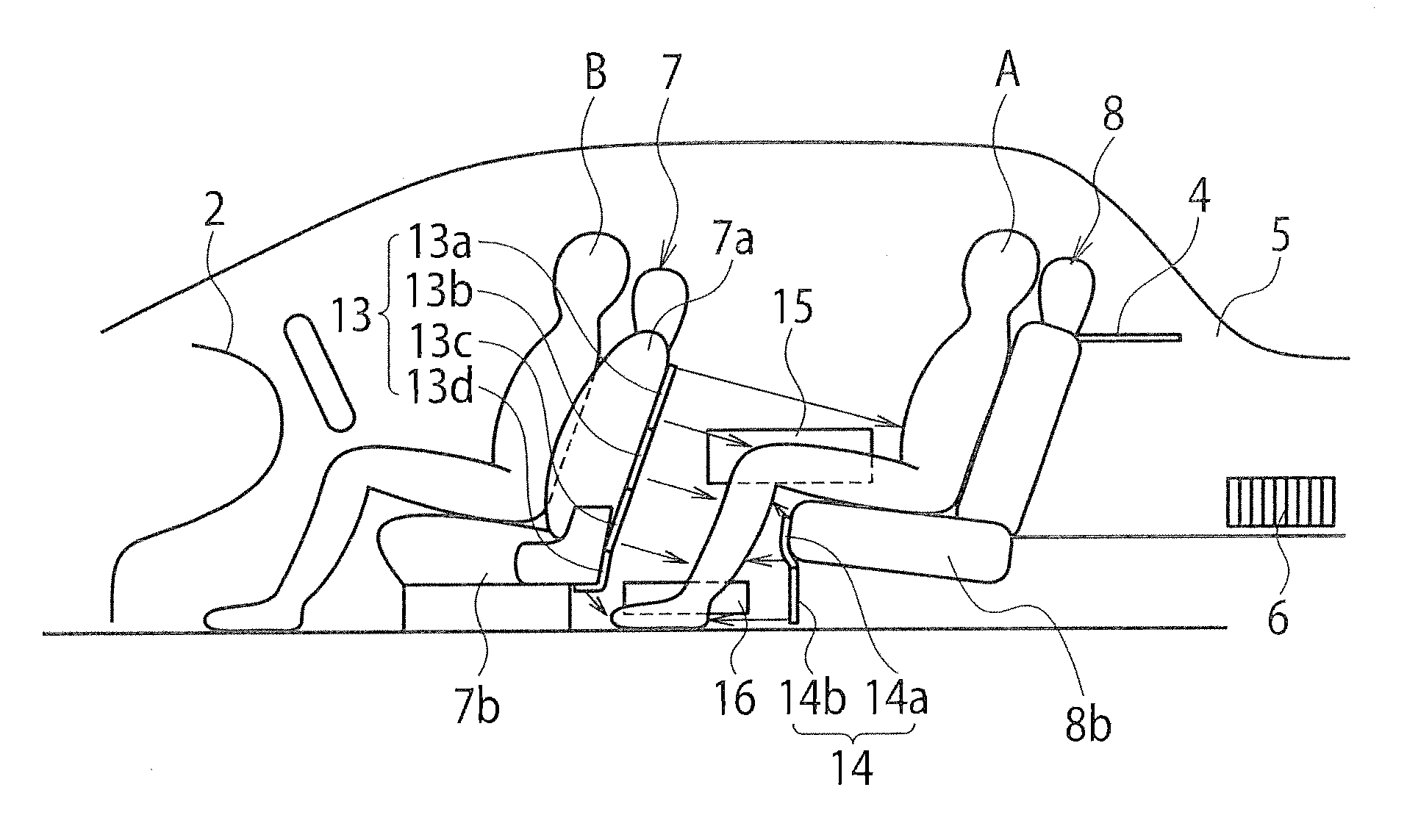
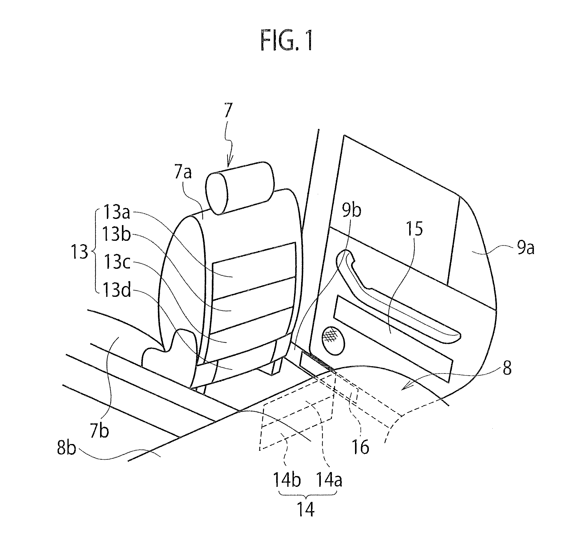
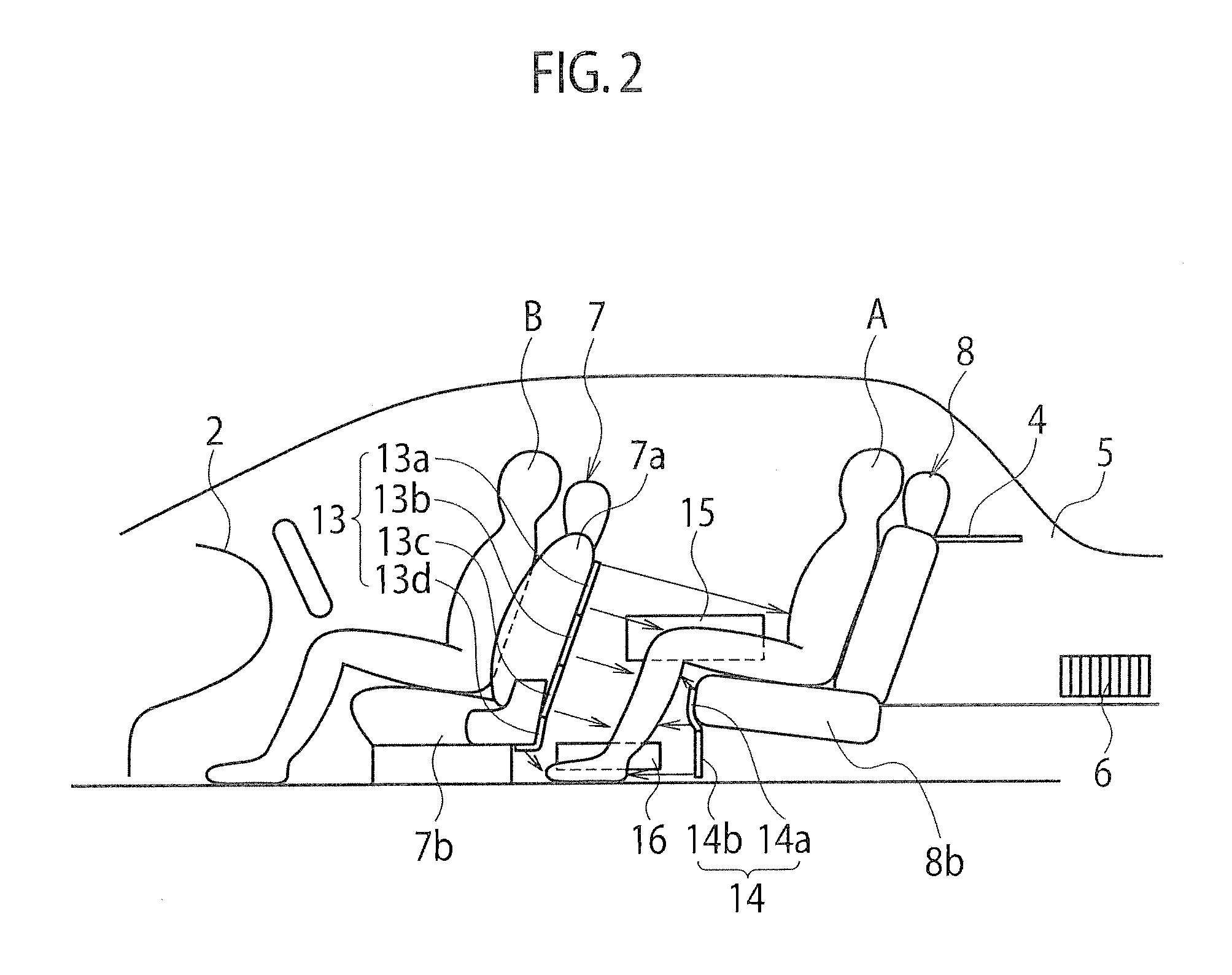
[0041]A first embodiment will be explained with reference to FIGS. 1 to 9. An air conditioning system for a vehicle includes a blower-type air-conditioner 1 and a radiant heating device 10 for a vehicle.
[0042]The air-conditioner 1 includes an air-conditioner unit 3 in an inside of a center console panel 2 (see FIGS. 8 and 9).
[0043]The air-conditioner unit 3 is provided with an outside air intake port and an inside air intake port (not shown). The air-conditioner unit 3 is provided with an intake door (not shown) that can selectively open the outside air intake port and the inside air intake port. Air outside a passenger compartment (outside air) or air inside a passenger compartment (inside air) can be selectively introduced into the air-conditioner unit 3 according to a position of the intake door.
[0044]In the air-conditioner unit 3, a blower, an evaporator and a heater are disposed sequentially from upstream to downstream along an introduced airflow. Outside air or inside air is i...
second embodiment
[0070]A second embodiment will be explained with reference to FIGS. 10 and 11. An air-conditioning system for a vehicle in the present embodiment has almost the same configurations as those of the system in the above first embodiment. Therefore, its identical or similar constituent elements are labeled with identical numerals and their redundant explanations will be omitted.
[0071]An air-conditioning system in the present embodiment includes, similarly to the above first embodiment, a blower-type air-conditioner 1 and a radiant heating device 10 for a vehicle, but the air-conditioner 1 can perform an economical heating operation in addition to a normal heating operation. Therefore, as shown in FIG. 10, an economical heating switch 39 is provided on a main operational panel 30A of the air-conditioner 1 disposed on the center console panel 2 in addition to an air-blow mode switch 34, an intake mode selection / temperature set switch 35, an air volume switch 36, a defroster switch 37, and...
PUM
 Abstract
Description
Claims
Application Information