Modification of an industrial vehicle to include a containment area and mounting assembly for an alternate fuel

Active Publication Date: 2013-03-21
GASEOUS FUEL SYST
22 Cites 27 Cited by

AI-Extracted Technical Summary

Problems solved by technology

These attempts serve to diminish adverse effects of control mechanisms which may be potentially harmful to the vehicle engine operation as well as being uneconomical.
Typical adverse effects include increased fuel consumption and wear on operative components.
As a result, many diesel engines associated with heavy duty and off-road vehicles are commonly operated at maximum or ne...

Method used

[0035]Therefore, in order to enhance the obstructed field of vision of an operator within the operator cab 16, the vehicle 20 may be additionally equipped with an auxiliary viewing facility comprising at least one camera and a viewing monitor or display. The at least one camera, not shown for purposes of clarity can be located in any of a plurality of appropriate positions and orientations on the vehicle 20 so as to enhance the obstructed view of the operator created by the exposed disposition of the mounting assembly 110. Similarly, the display or monitor is located preferably on the interior of the operator cab or in another appropriate location which is clearly viewable by an operator so as to overcome the at least laterally obstructed view of the operator from the operator area 14 or enclosed cab 16.
[0036]As further represented in FIGS. 1 and 2, additional structural features define by or associated with the containment area 10 and the operatively disposed mounting assembly 110, as represented in FIG. 2, includes the mounting assembly 110 disposed in at least partially enclosed or at least minimally covered relation relative to a frontal portion 22 of the dump truck body 24. More specifically, the mounting assembly 110 is disposed at least partially beneath and in underlying relation to the overlying position of the frontal portion 22 of the dump truck body 24. With reference to FIG. 3, a frontal portion of the containment area 10 still remains at least partially open. Therefore, the placement or installation of the mounting assembly 110 within the containment area 12 may be accomplished, at least in part, by a raising or opening of the truck body 24 such that the frontal portion 22 thereof is outwardly spaced away from the containment area 12. Appropriate hooks or like connectors 11 are mounted on the housing 112 of the mounting assembly 110 to facilitate its positioning, such as by crane or other appropriate lifting device. Hoverer, as clearly represented in FIG. 2 the operative disposition of the mounting assembly 110 is located immediately and laterally adjacent to the operator area 14 including the enclosed cab 16 so as to abut or be minimally spaced away from a the lateral sidewall portion 18 as generally set forth above. Moreover, when the installation of the mounting assembly 110 is complete, the dump truck body 24 may be conventionaly raised and lowered so as to assume and facilitate the normal operation of the vehicle 20.
[0037]With primary reference to FIGS. 4-6, the present invention is directed to a mounting assembly generally indicated as 110 including a movably interconnected housing generally indicated as 112. The mounting assembly 110 is specifically, but not exclusively, intended for use on heavy duty “mine haul” vehicles, bulldozers or other vehicles of the type generally set forth above. As emphasized herein the mounting assembly is specifically dimensioned and configured to facilitate its operative placement within the containment area 10 defined on or considered a part of the mine haul dump truck vehicle.
[0039]The base 116 may also include a connecting assembly comprising at least one but in certain practical applications a plurality of at least two hinge structures generally indicated as 124. Each of the hinge structures 124 are connected to an appropriate link 126 or like structure secured to an under portion of the housing 114 as clearly represented. The structural and operative features of each of the one or more hinge structures 124 is such as to facilitate the selective positioning or movement of the housing 112 as well as the containment structure or fuel tanks 114 between a first orientation, as represented in FIGS. 2 and ...

Benefits of technology

[0017]Accordingly, the mounting assembly of the present invention comprises a containment structure for the fuel supply (LNG) in the form of at least one or a plurality of at least two fuel tanks. Each of the one or more fuel tanks stores the LNG or other fuel on the interior thereof during periods of non-use or operation of the vehicle. The mounting assembly further includes a housing structured to at least partially enclose the one or more fuel tanks on the interior thereof. A base is mounted on the vehicle in supporting relation to both the housing and the containment structure or fuel tanks. Therefore, the containment structure is at least partially enclosed and accordingly protected against unintended impact or contact by other objects, vehicles, etc. in the working environment of the vehicle on which the fuel supply and containment structure are disposed.
[0018]Therefore, one feature of the system and accompanying structural features of the present invention includes the aforementioned mounting assembly structured for containment and support of the alternate fuel supply. In addition and at least partially for the reasons set forth above, another feature of the present invention comprises the establishment of a predetermined containment area defined on and considered a part of the vehicle. Moreover, the containment area is defined and structured in a location which facilitates the operative communication of the alternate fuel supply, disposed within the mounting assembly, with the remainder of the fuel control system serving to regulate the distribution of fuel to the powering engine of the vehicle. Moreover, the containment area and the operatively disposed mounting assembly are collectively positioned in laterally adjacent and exposed relation to an operator area of the mine haul vehicle. In addition, the mine haul vehicle typically includes the operator area defined by an enclosed operator cab.
[0019]The mounting assembly and th...

Abstract

A system and attendant structural components for incorporating an alternate fuel supply, such as of the type used in combination with a conventional distillate fuel, to power a heavy duty industrial vehicle, such as a mine haul dump truck. The system and attendant structure includes a mounting assembly structured for containment and support of the alternate fuel and a containment area disposed on the vehicle and structured and dimensioned to retain the mounting assembly therein. The containment area and the mounting assembly are disposed in laterally adjacent, exposed relation to an operator area of the mine haul truck, wherein the mounting assembly and the containment area are cooperatively disposed and structured to facilitate storage of the alternate fuel and operative communication and distribution thereof with the powering engine of the mine haul vehicle.

Application Domain

Technology Topic

Image

  • Modification of an industrial vehicle to include a containment area and mounting assembly for an alternate fuel
  • Modification of an industrial vehicle to include a containment area and mounting assembly for an alternate fuel
  • Modification of an industrial vehicle to include a containment area and mounting assembly for an alternate fuel

Examples

  • Experimental program(1)

Example

[0032]Like reference numerals refer to like parts throughout the several views of the drawings.
DETAILED DESCRIPTION OF THE PREFERRED EMBODIMENT
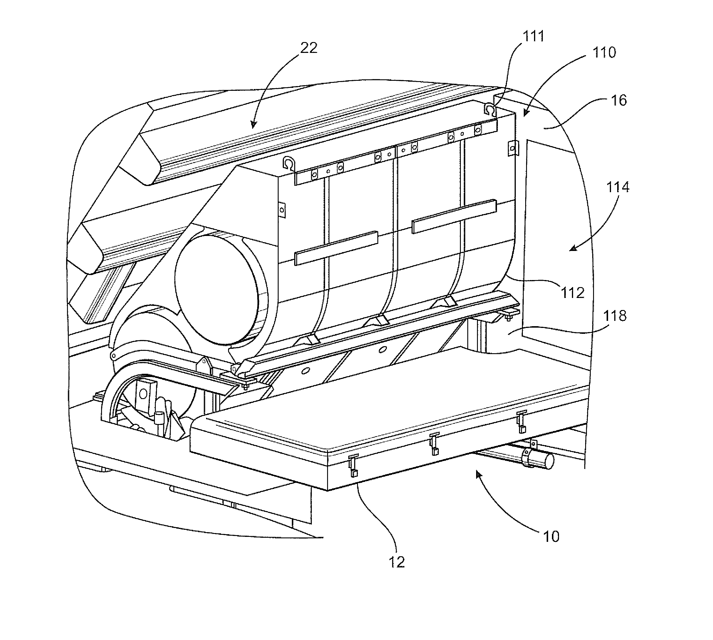
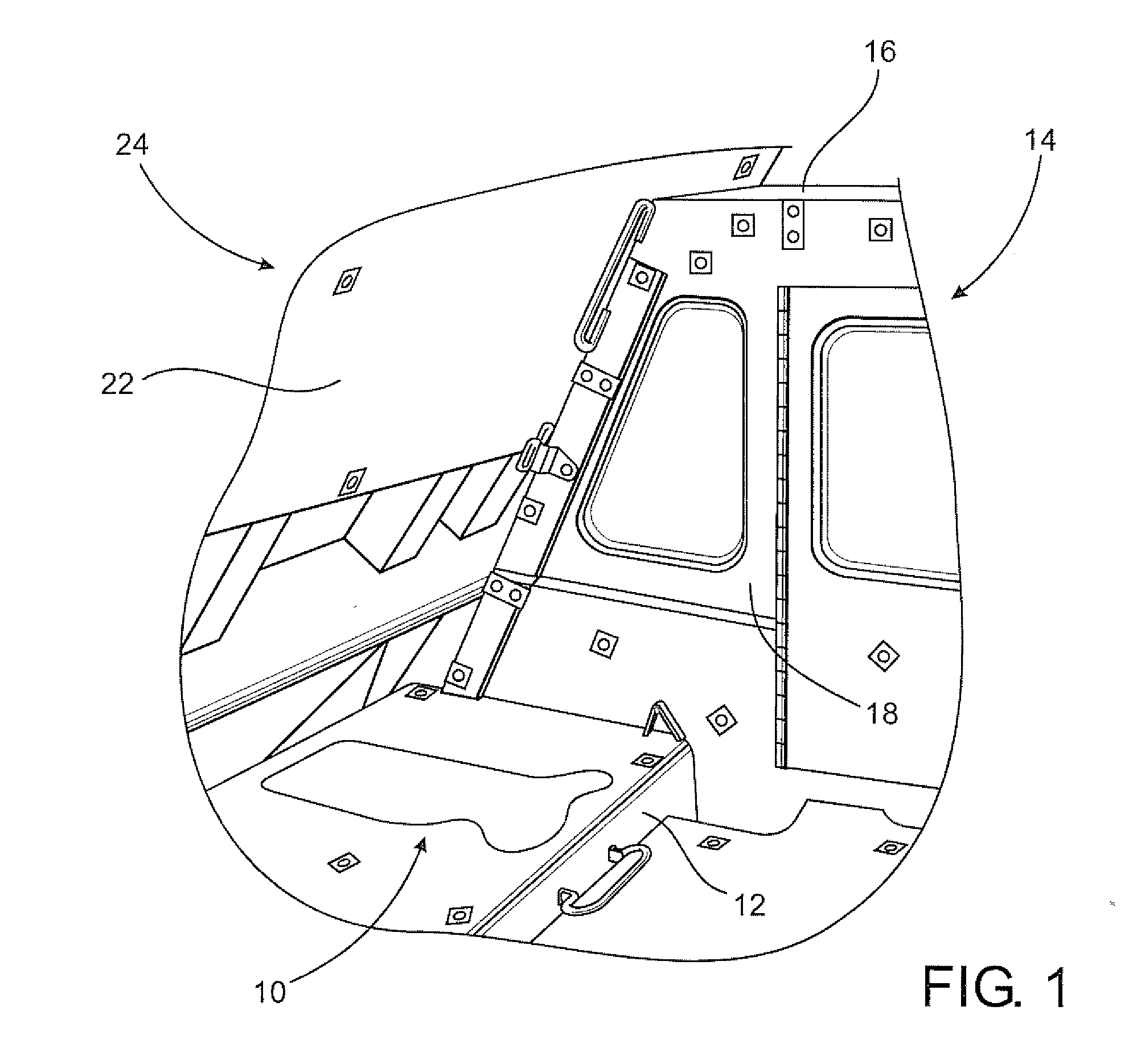
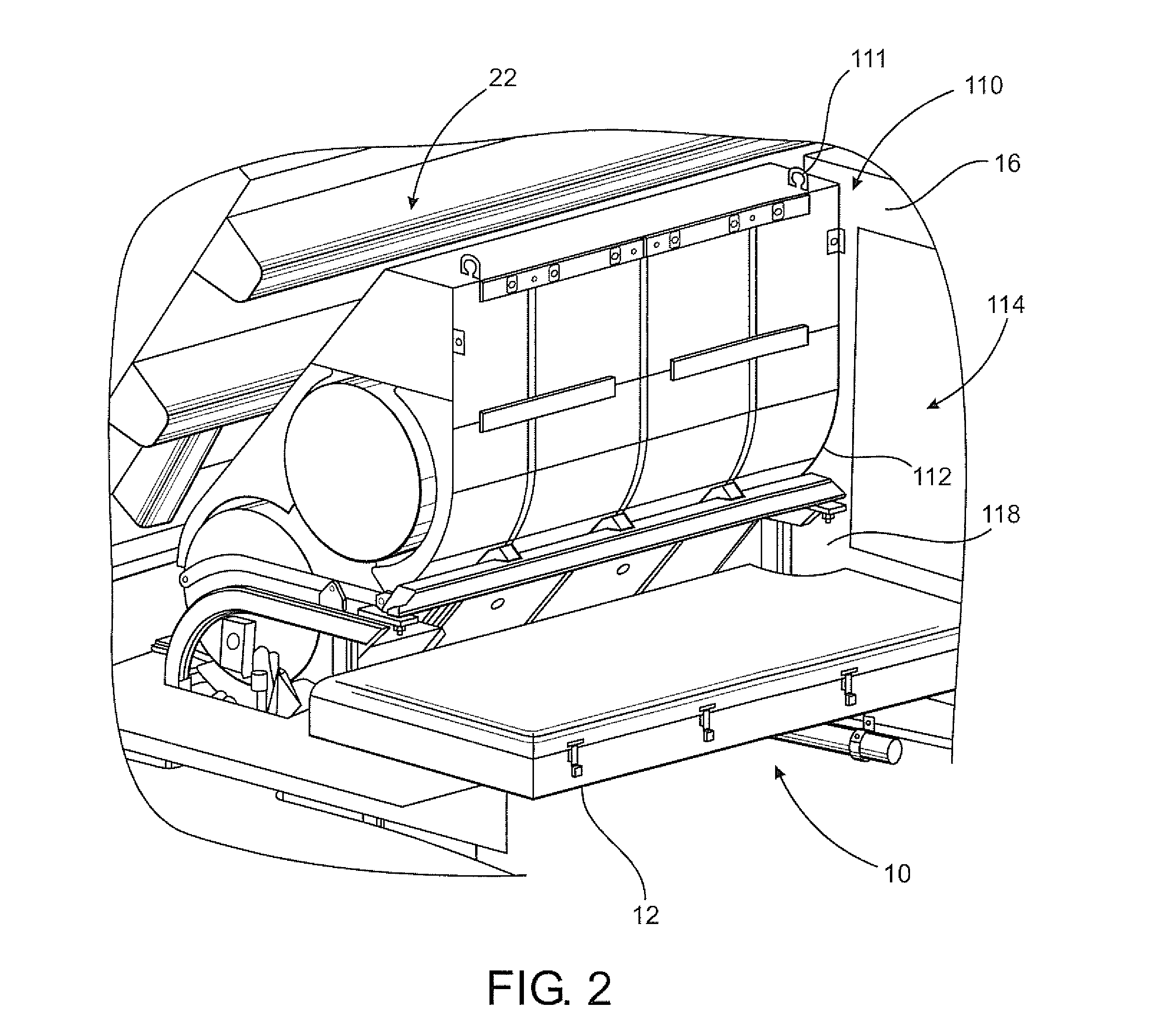
[0033]As represented in FIGS. 1 through 3, the present invention is directed to a system, cooperative structuring and attendant facilities for operatively disposing a mounting assembly 110 within a containment area generally indicated as 10. The containment area 10 is disposed on and is considered and integrated part of an industrial or commercial vehicle specifically including a mine haul dump truck vehicle generally indicated as 20 in FIG. 3. As such, the containment area 10 includes a platform 12 and a sufficiently dimensioned and configured are to operatively dispose at least one preferred embodiment of the mounting assembly generally indicated as 110 in FIG. 2 and described in greater detail in FIGS. 4 through 6.
[0034]As set forth above, the industrial or commercial vehicle 20 may be in the form of a mine haul dump truck vehicle such as, but not limited to a caterpillar; model 777. However, as set forth above the versatility of the mounting assembly 110 and the dimension, configuration and overall structure of the cooperative containment area 10 allows the mounting assembly to be used on a variety of similar industrial or commercial vehicles including different makers and models of such vehicles, as indicated above. Further by way of reference and clarity, the containment area 10 is generally located on the vehicle, as at 10′ and with reference to both FIGS. 1 and 3, the containment area 10, 10′ is located immediately and laterally adjacent to an operator area generally indicated as 14. Moreover, typical of mine land haul vehicles 20, the containment area 14 comprises and enclosed operator cab 16 having an exterior wall or like partition member 18 disposed in at least partially confronting or immediately adjacent relation to the containment area 10 including the platform 12. As such, operative disposition of the mounting assembly 110 in the containment area 10 and on or at least directly associated with a platform 12 serves to disposed the mounting assembly 110 in immediate laterally adjacent relation to the operator area 14 and/or enclosed operator cab 16. The disposition of the containment area 10 in the laterally adjacent to the operator area 14 further serves to dispose the mounting assembly 110 in a visually obstructing or “exposed” relation relative to the interior of the operator cab 16. As a result the field of vision normally available to an operator in the operator cab 16 will be somewhat blocked of hindered due to the “exposed” laterally adjacent relation of the mounting assembly 110 through the operator area 14 and more specifically the operator cab.
[0035]Therefore, in order to enhance the obstructed field of vision of an operator within the operator cab 16, the vehicle 20 may be additionally equipped with an auxiliary viewing facility comprising at least one camera and a viewing monitor or display. The at least one camera, not shown for purposes of clarity can be located in any of a plurality of appropriate positions and orientations on the vehicle 20 so as to enhance the obstructed view of the operator created by the exposed disposition of the mounting assembly 110. Similarly, the display or monitor is located preferably on the interior of the operator cab or in another appropriate location which is clearly viewable by an operator so as to overcome the at least laterally obstructed view of the operator from the operator area 14 or enclosed cab 16.
[0036]As further represented in FIGS. 1 and 2, additional structural features define by or associated with the containment area 10 and the operatively disposed mounting assembly 110, as represented in FIG. 2, includes the mounting assembly 110 disposed in at least partially enclosed or at least minimally covered relation relative to a frontal portion 22 of the dump truck body 24. More specifically, the mounting assembly 110 is disposed at least partially beneath and in underlying relation to the overlying position of the frontal portion 22 of the dump truck body 24. With reference to FIG. 3, a frontal portion of the containment area 10 still remains at least partially open. Therefore, the placement or installation of the mounting assembly 110 within the containment area 12 may be accomplished, at least in part, by a raising or opening of the truck body 24 such that the frontal portion 22 thereof is outwardly spaced away from the containment area 12. Appropriate hooks or like connectors 11 are mounted on the housing 112 of the mounting assembly 110 to facilitate its positioning, such as by crane or other appropriate lifting device. Hoverer, as clearly represented in FIG. 2 the operative disposition of the mounting assembly 110 is located immediately and laterally adjacent to the operator area 14 including the enclosed cab 16 so as to abut or be minimally spaced away from a the lateral sidewall portion 18 as generally set forth above. Moreover, when the installation of the mounting assembly 110 is complete, the dump truck body 24 may be conventionaly raised and lowered so as to assume and facilitate the normal operation of the vehicle 20.
[0037]With primary reference to FIGS. 4-6, the present invention is directed to a mounting assembly generally indicated as 110 including a movably interconnected housing generally indicated as 112. The mounting assembly 110 is specifically, but not exclusively, intended for use on heavy duty “mine haul” vehicles, bulldozers or other vehicles of the type generally set forth above. As emphasized herein the mounting assembly is specifically dimensioned and configured to facilitate its operative placement within the containment area 10 defined on or considered a part of the mine haul dump truck vehicle.
[0038]More specific structural details of the mounting assembly 110 of the embodiment of FIGS. 2 and 4-6 include the housing 112 being structured to include the alternate fuel supply disposed within a containment structure 10. The containment structure 10 comprises at least one but in certain practical applications, a plurality of fuel tanks 114. As also represented, the housing 112 is supported and interconnected to the vehicle 20 by means of a base assembly, generally indicated as 116. The base 116 includes a plurality of support legs 118 each of which include leg segments 120 and 120′ having the lower end thereof fixedly secured, such as by welding the accompanying mounting pads 122 to the platform 12 or other appropriate portion of the containment area 10 of the vehicle 20, on which the mounting assembly 110 is disposed.
[0039]The base 116 may also include a connecting assembly comprising at least one but in certain practical applications a plurality of at least two hinge structures generally indicated as 124. Each of the hinge structures 124 are connected to an appropriate link 126 or like structure secured to an under portion of the housing 114 as clearly represented. The structural and operative features of each of the one or more hinge structures 124 is such as to facilitate the selective positioning or movement of the housing 112 as well as the containment structure or fuel tanks 114 between a first orientation, as represented in FIGS. 2 and 6, and a second substantially upright orientation, as represented in FIGS. 4 and 5. Accordingly, the connecting hinge structures 124 serve to movably interconnect the housing 112 to the containment area 10 and further serve to support the housing 112 at least when the housing is in the second orientation of FIGS. 4 and 5. The disposition of the hinge structures 124 also add to the support of the housing 112 when it is in the first orientation, as clearly represented in FIG. 6. The one or more hinge structures 124 may be considered a part of the base 16 due to their support of the housing 112 when at least in the second orientation and most probably when in both the first and second orientations. However, dependent upon the structure, configuration and dimension of the mine haul vehicle 20 and containment area 10 in which the mounting assembly 110 is disposed, the one or more hinge structures 124 may be considered independent of the base 116 by virtue of their location being not directly adjacent to or operatively associated with the base 116.
[0040]Further with regard to the selective positioning of the housing 112 in either the first or second orientations, the mounting assembly 110 further includes a retaining assembly comprising at least one, but preferably a plurality of at least two retaining arms or bars 128. The one or more retaining arms 128 serve to maintain and at least partially support the housing 112, at least when it is in the second orientation as clearly demonstrated in FIGS. 2, 4 and 5 when in their operative position. Each of the retaining arms 128 include opposite ends removably connected, as at 130, to the correspondingly disposed support arm 118. The opposite end of each of the retaining arms 128 is removably connected, as at 131, to the housing 112 and more specifically to a brace or cross brace structure 132.
[0041]Moreover, each of the retaining arms 128 is removed from the stored orientation and disposed in the supporting orientation of FIGS. 4 and 5. When in such a supporting orientation, the opposite end 130 is removably connected to the upstanding connecting flange 139, by a threaded knob or like connector. The removable but stable interconnection of the opposite ends 130 and 131, as at 130′ and 131′, to the mounting flange 139 and the base 132, respectively, will serve to assure that the retaining arms 128 are maintained in their operative, supporting, retaining position between the base 116 and the housing 112 and/or brace 132. However, the removable interconnection of each of the retaining arms 128 in their supporting, retaining position facilitates the easy disconnection of the retaining arms 128 for selective disposition in their stored orientation in order to dispose the housing 112 in the first orientation.
[0042]The stability of the containment structure, comprising the one or more fuel tanks 114 within the interior of the housing 112, is further enhanced by a stabilizing assembly 144 also at least partially disposed on the interior of the housing 112. The stabilizing assembly 144 includes at least one but preferably a plurality of stabilizing members 146 disposed in spaced relation to one another and collectively extending along the length of the one or more fuel tanks 114 defining the containment structure for the fuel supply. In addition, the stabilizing members 46 may be disposed on opposite sides of fuel tanks 114. In addition, each or at least some of the stabilizing members 146 include a recessed segment or portion 148 at least partially dimensioned and configured to the corresponding exterior configuration of each of the fuel tanks 114. As such, the plurality of stabilizing members 146 can be defined as collectively and at least partially surrounding and/or “sandwiching” the plurality of fuel tanks 114 there between. By virtue of this cooperative disposition and structure, movement or inadvertent, unintended displacement of the one or more fuel tanks 14 within the interior of the housing 112 is eliminated or significantly restricted. In addition, the stabilizing assembly 146 can be defined by a plurality of the stabilizing members 148 which may vary in number, size, configuration, etc. so as to accommodate a confronting engagement or relation with the one or more fuel tanks 114 in a manner which facilitates the ability to restrict the displacement or movement of the fuel tanks 114 within the interior of the housing 112, whether the housing 112 is in either the aforementioned first or second orientations.
[0043]The versatility of the containment area 10 is further represented in at least partially schematic form in the embodiment of FIG. 7. In one preferred embodiment the mounting assembly 110 of the embodiment of FIGS. 2 and 4 through 6, may be operatively disposed in the containment area 10. However, other mounting assemblies having a variety of different but appropriate structural features may be utilized with a variety of different vehicles, specifically including mine haul vehicles, as set forth in detail herein. More specifically, in the additional preferred embodiment of FIG. 7 the mounting assembly is generally indicated as 210 and includes a base 212 having a support frame or like structure comprising a plurality of legs 214. In addition, a containment structure generally indicated as 216 is in the form of at least one fuel tank for storage and support for the alternate and/or auxiliary fuel supply such as (LNG). As with the mounting assembly 110 the additional preferred embodiment of the mounting assembly 210 is located in the containment area 10 and in immediate, laterally adjacent relation to the operator area 14 which may be in the form of the enclosed operator cab 16. As such at least a portion of the mounting assembly 210 including, but not limited to, the containment structure or one or more fuel tanks 216 are positioned in an “exposed” or visually obstructing relation as relates to the field of vision of an operator within the compartment area 14. Accordingly, the aforementioned auxiliary viewing assembly, including at least one camera and a display or monitor, is also provided for use by an operator when the mounting assembly 210 is operatively disposed within the containment area 10.
[0044]As also set forth above, the containment area 10 and the mounting assembly 210 are disposed in underlying relation to at least a frontal portion 22 of the dump truck bed 24 so as to be partially enclosed and/or protected thereby when the dump truck bed 24 is in its closed or lowered position. However, the containment area 10 is still preferably in the frontal, at least partially open location 10′ of the vehicle 20 as represented in FIG. 3.
[0045]Since many modifications, variations and changes in detail can be made to the described preferred embodiment of the invention, it is intended that all matters in the foregoing description and shown in the accompanying drawings be interpreted as illustrative and not in a limiting sense. Thus, the scope of the invention should be determined by the appended claims and their legal equivalents.
[0046]Now that the invention has been described,

PUM

no PUM

Description & Claims & Application Information

We can also present the details of the Description, Claims and Application information to help users get a comprehensive understanding of the technical details of the patent, such as background art, summary of invention, brief description of drawings, description of embodiments, and other original content. On the other hand, users can also determine the specific scope of protection of the technology through the list of claims; as well as understand the changes in the life cycle of the technology with the presentation of the patent timeline. Login to view more.

Similar technology patents

Implant insertion tool

Owner:STRYKER EURO OPERATIONS HLDG LLC

Compressor and assembly method thereof

ActiveUS20120243982A1Facilitate operationReduce roller sizePump componentsMetal-working apparatusTilt sensorEngineering
Owner:MITSUBISHI HEAVY INDUSTIES COMPRESSOR

Classification and recommendation of technical efficacy words

  • Easily view
  • Facilitate operation

Cordless pool cleaning robot

InactiveUS20070067930A1Facilitate easy removalFacilitate operationGymnasiumSwimming poolsUser interfaceCordless
Owner:MAYTRONICS

Change navigation toolkit

InactiveUS20160321583A1Facilitate operationFacilitates knowledgeNatural language data processingOffice automationOrganizational spaceBusiness transactions
Owner:ACCENTURE GLOBAL SERVICES LTD

Clean power system

Owner:EATON INTELLIGENT POWER LIMITED
Why Eureka
Try Eureka