Sliding visor

a technology of sliding visor and visor body, which is applied in the direction of sun visor, roof, transportation and packaging, etc., can solve the problems of reducing the production efficiency of sliding visors. , to achieve the effect of improving the sliding visor

Active Publication Date: 2013-03-21
IRVIN AUTOMOTIVE PROD LLC
View PDF19 Cites 14 Cited by
  • Summary
  • Abstract
  • Description
  • Claims
  • Application Information

AI Technical Summary

Benefits of technology

[0019]Still another advantage of the present invention may be that it provides a sliding visor that incorporates ultrasonic weld joints and profile snaps that allow for a robust, zero flex interfacing between the two half shells of the visor body.
[0020]According to the present invention, the foregoing and other objects and advantages are obtained by a novel design for a sliding visor for use in a vehicle. The sliding visor generally comprises a pivot rod and a floating carrier slidingly arranged on the pivot rod. The visor further comprises a first and second shell engagable to form a visor a body. The floating carrier is slidingly retained between the first shell and the second shell, wherein the floating carrier having a first surface and a first finger engaging the first shell and a second surface and a second finger engaging the second shell of the visor body. The visor further comprises a floating detent engaged with the pivot rod and arranged within the floating carrier without being directly inter

Problems solved by technology

Advances in design can often add complexities to the manufacturing processes for interior components.
Generally, in the prior art, manufacturing simplicity continues to drive innovations in the automotive industry, loss of quality and performance in the manufacturing of components for the sake of facilitating production is seldom, if ever, acceptable.
The construction of the visors having such a design is relatively time intensive.
Moreover, the various slides, journals, retainers, etc., utilized in the

Method used


Image

  • Sliding visor
  • Sliding visor
  • Sliding visor

Examples


Embodiment Construction

)

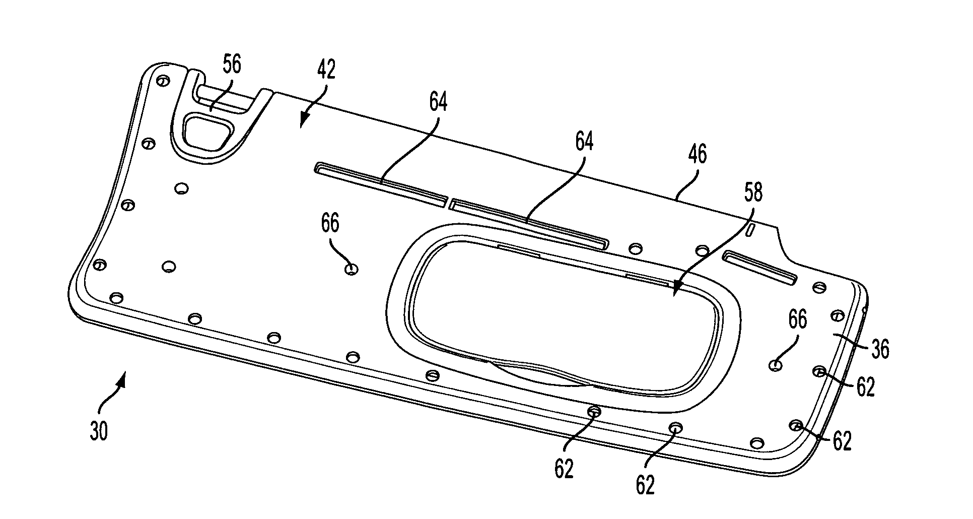
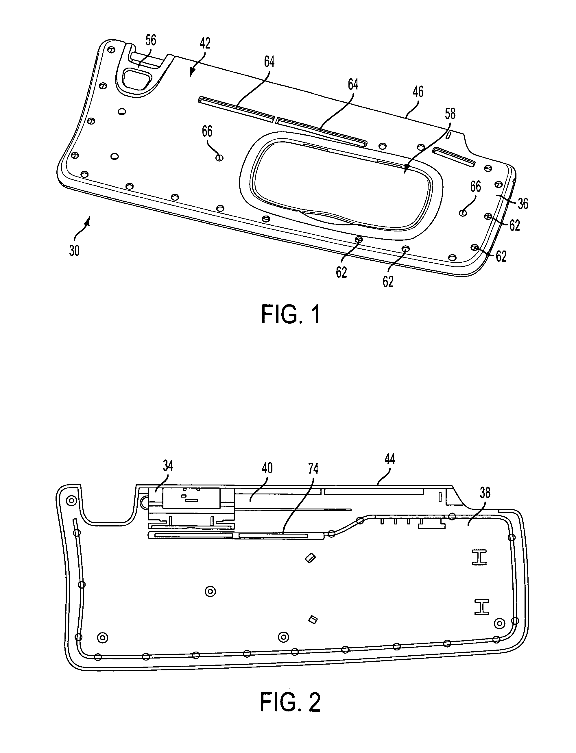
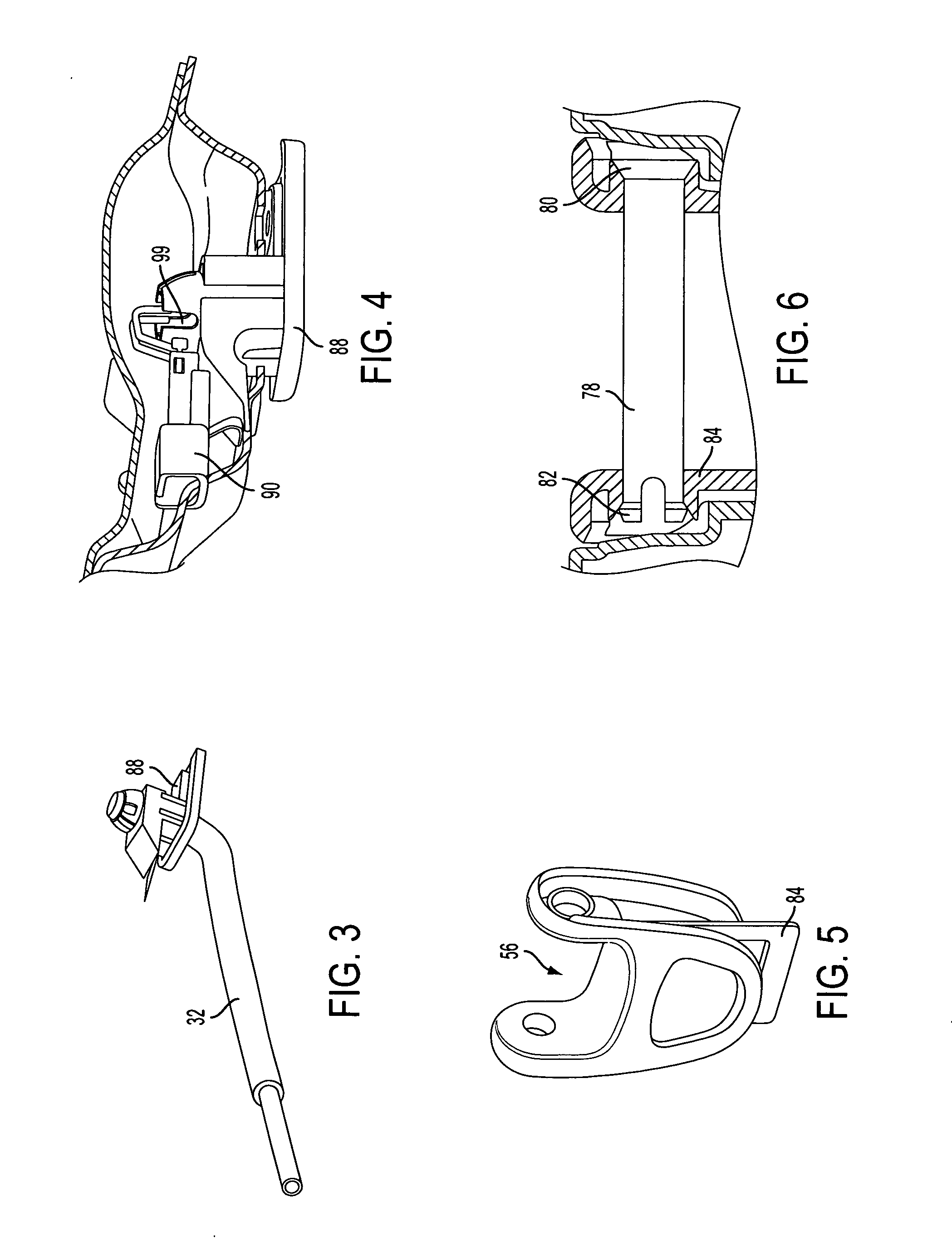
[0064]Referring to the drawings, there is shown a sliding visor 30 according to an embodiment of the present invention. Generally, the present invention broadly provides a clam shell type vehicle sun visor 30 having a pivot rod 32 mounted to a floating carrier 34, wherein the pivot rod 32 and floating carrier 34 are slidably captured during assembly with the single step of attaching visor shell portions 36, 38 together. The floating carrier 34 thus rides in the visor body 42 itself rather than a separate carrier and is preferably retained between surfaces and / or features, such as channels 40 molded integrally within the shell portions 36, 38. Similarly, the pivot rod 32 rides in the visor body 42, and a separate bracket, bezel or similar piece is not necessary to support the pivot rod 32. Related aspects of the present invention include methods for manufacturing a sun visor 30 also described herein. Furthermore, it should be noted that the visor 30 as shown in the present applicati...


PUM

PropertyMeasurementUnit
Angleaaaaaaaaaa
Angleaaaaaaaaaa
Interferenceaaaaaaaaaa

Abstract

A sliding sun visor for use in a vehicle is disclosed. The sun visor includes a first and second visor body shell. At least one of the shells having a retaining channel for engaging and retaining a floating carrier on a visor pivot rod. It is also contemplated that the sun visor may have a snap in vanity system and rotating pin on a D-ring associated therewith. The visor body also may include a wire routing option to route a wire from the electrical system of a vehicle to a light bulb in a vanity.

Description

BACKGROUND OF THE INVENTION[0001]1. Field of the Invention[0002]The present invention generally relates to a movable sun visor for interior use in a vehicle, and more particularly relates to a sun visor wherein the visor body includes two visor body halves or shells adapted to close about and slidably retain a carrier attached to a pivot rod.[0003]2. Description of Related Art[0004]Sun visors are well known and widely used in the prior art. Many different types of designs have been successfully employed in vehicles over the years. Many of these prior art visors have been developed in a variety of ways through which visor bodies and other interior components may be constructed and mounted within the vehicle. Advances in design can often add complexities to the manufacturing processes for interior components. There has been and continues to be a premium in the automotive industry on cost savings, and improvements in the efficiency and speed in the manufacturing processes for such comp...

Claims


Application Information

Patent Timeline
IPC IPC(8): B60J3/02B32B7/04
CPCB60J3/023Y10T29/49876B60J3/0282B60J3/0265B60Q3/252B60J3/0208
Inventor HUFF, DAVID LEEHINDS, LESLIE RAYMONDBUSHA, BRYAN WESLEYWOODWARD, DONALD JOSEPHWIECZOREK, JOSEPH PETER
Owner IRVIN AUTOMOTIVE PROD LLC
Why Eureka
Try Eureka