Transmitter module for use in a modular power transmitting system

a power transmitting system and transmitter module technology, applied in the direction of coupling device details, coupling device connections, inductances, etc., can solve the problems of fixed size, inability to extend, and predetermined size of the system, so as to enhance the mechanical stability of the power surface

Active Publication Date: 2013-03-21
KONINKLIJKE PHILIPS ELECTRONICS NV
View PDF2 Cites 275 Cited by
  • Summary
  • Abstract
  • Description
  • Claims
  • Application Information

AI Technical Summary

Benefits of technology

[0011]In an embodiment of transmitter module, the outer periphery is further provided with an extending part at a first periphery position and a complementary cut-out part at a second periphery position, and, when the module is arranged in the power surface, the first position being adjacent to the second position of a neighboring module for providing a mechanical fixing via the extending part and the cut-out part. This has the advantage that mechanical stability of the power surface is enhanced.
[0012]In an embodiment of transmitter module, the interconnection units, when the module is arranged in the power surface, have a configuration of female connectors for connecting with neighboring transmitter modules via interconnector pins parallel to the power surface. This has the advantage that, at the outer edges of the power surface, no contact pins are extending.
[0013]In an embodiment of transmitter module, the interconnection units, when the module is arranged in the power surface, have a electrical configuration of connections arranged along the periphery at a first periphery position for connecting with a complementary connections at a second periphery position at the neighboring transmitter modules, the first and second positions matching when the modules are arranged as intended and not matching when the modules are arranged otherwise, for providing a reverse connection safety. It is to be noted that modules may be symmetric in at least one rotational position. The features have the effect that modules, when properly arranged, will have connection as intended, while positioning a module in a different rotational position result in the interconnection units being at different, non-matching, positions, called reverse connection safety.
[0014]In an embodiment of transmitter module, the interconnection units are arranged for providing a communication connection between the transmitter module and the other transmitter modules. This has the effect that the controller is enabled to exchange data among the modules. Advantageously power transfer and other tasks can be coordinated across modules, e.g. when a receiver is positioned across a module boundary.
[0015]In an embodiment of transmitter module, the controller is arranged for determining position and orientation of the transmitter module with respect to other transmitter modules arranged in the power surface. Determining of a transmitter module in this document is the function that the module communicates with other modules connected via its interconnection units and detects where and how it is positioned in the power surface with respect to the other modules. Subsequently the module assigns itself to a position and orientation within the power surface. This has the advantage that modules now can respond to commands indicating a specific position in the power surface, e.g. for activating one or more specific receivers.
[0016]In an embodiment of transmitter module, the transmitter module comprises a memory for storing identification information for identifying the transmitter module, when the module is arranged in the power surface. The identification information may be stored in a permanent memory, hardwired, or switchable, e.g. set during manufacture or during an installation phase. This has the advantage that the module can be individually addressed.

Problems solved by technology

The known wireless inductive power system has the problem, that the size of the transmitter area is pre-determined.
However, in many cases, the needed area may vary, such that a system with pre-determined size lacks flexibility.
However, then the size is fixed and cannot be extended.
If two or more of the predetermined size systems are put together, gaps between the systems will remain, because the borders of these systems are not designed to be combined.
At these positions, the operation (e.g. power transmission) is not properly provided.
Furthermore, the individual systems are not designed to cooperate with each other.

Method used


Image

  • Transmitter module for use in a modular power transmitting system
  • Transmitter module for use in a modular power transmitting system
  • Transmitter module for use in a modular power transmitting system

Examples


Embodiment Construction

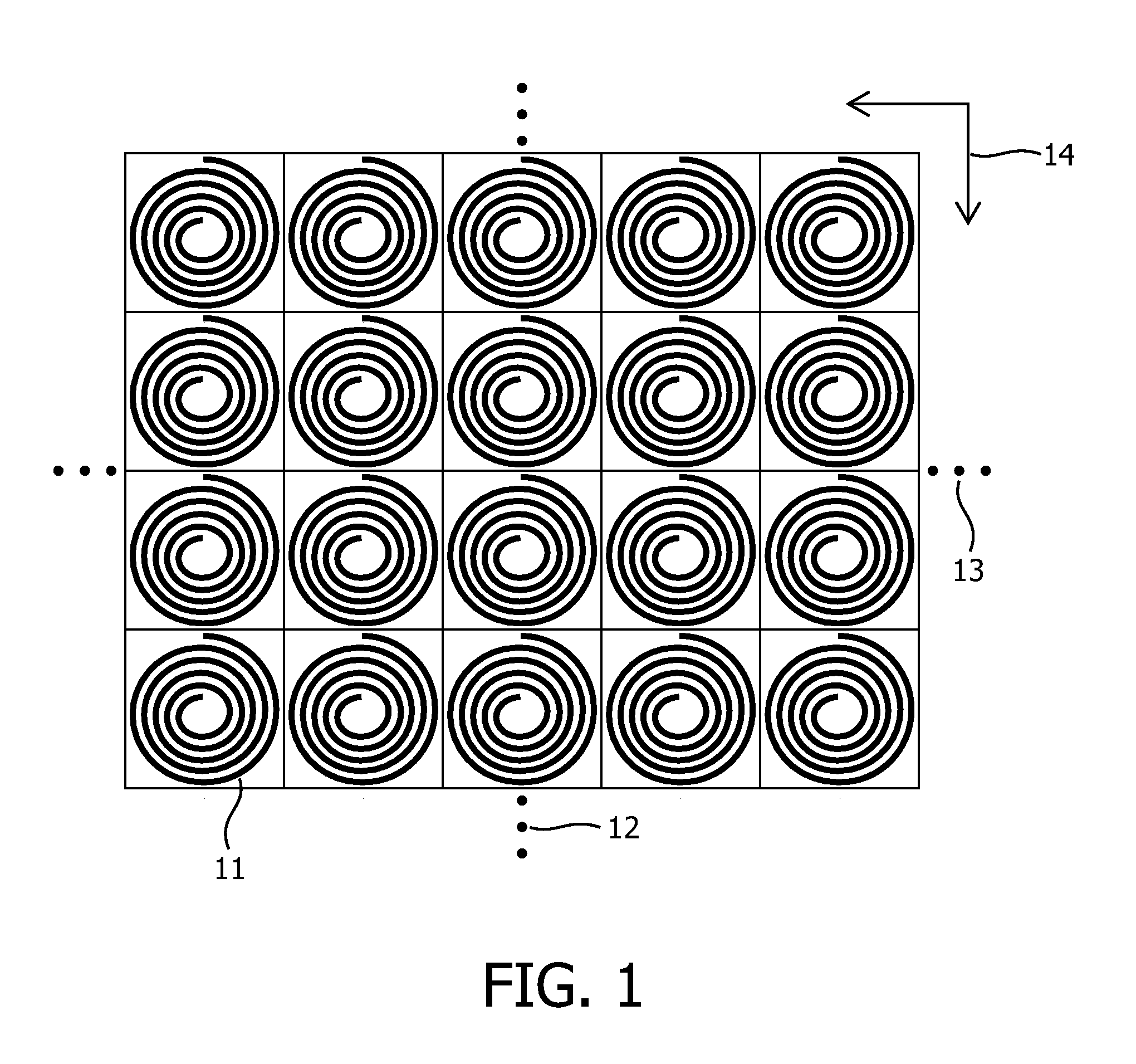
[0042]FIG. 1 shows a regular square arrangement of transmitter cells. An arrangement of transmitter coils 11 is shown; the coils being positioned in square areas as indicated by drawn lines. The size of the power surface constituted by the coils as indicated by arrow 14 is predetermined, and can be selected by extending the surface in the vertical or horizontal directions as indicated by vertical dots 12 and horizontal dots 13. Various similar arrangements are possible, for example also a triangular arrangement is possible.

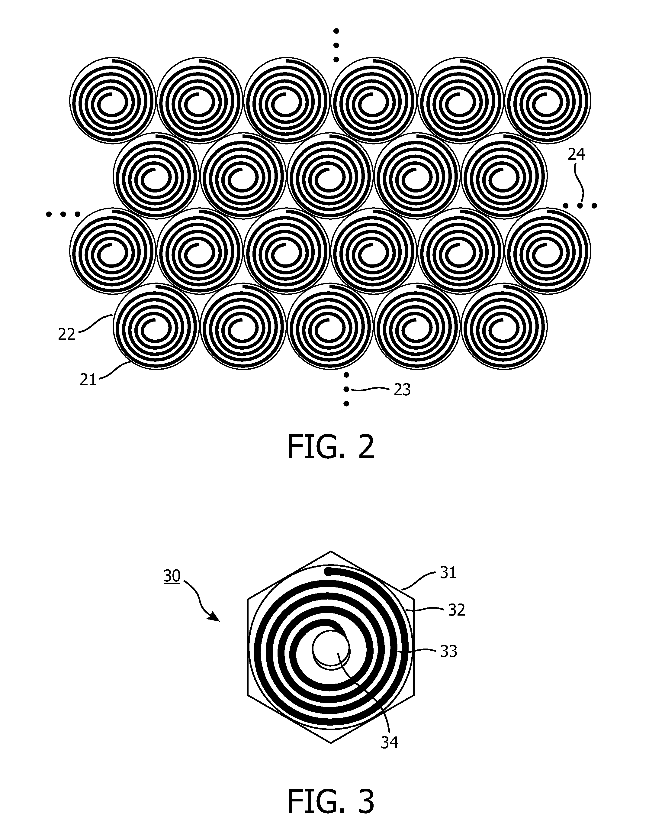
[0043]FIG. 2 shows a regular hexagonal arrangement of transmitter cells. An arrangement of transmitter coils 21 is shown; the coils being positioned in hexagonal areas 22 as indicated by thin dotted lines. The size of the power surface constituted by the coils is predetermined, and can be selected by extending the surface in the vertical or horizontal directions as indicated by vertical dots 23 and horizontal dots 24. In such predetermined regular arrangements lik...


PUM

PropertyMeasurementUnit
thicknessaaaaaaaaaa
areasaaaaaaaaaa
electrical configurationaaaaaaaaaa

Abstract

A modular power transmitting system comprises multiple transmitter modules being connected together for transmitting power inductively to a receiver. The transmitter module is connected with other transmitter modules for transmitting power inductively to the receiver, wherein the transmitter module (40) comprises at least one transmitter cell (30), each transmitter cell having one transmitter coil (33) by which the transmitter cell transmitting power to the receiver, the transmitter module having an outer periphery (45) being shaped so as to fit to neighboring transmitter modules for forming an power transmitting surface, the at least one transmitter cell being arranged such that the power transmitting surface is constituted by an uninterrupted pattern of adjacent transmitter coils extending in said surface, and interconnection units (110,111) for connecting with neighboring transmitter modules for sharing a power supply.

Description

FIELD OF THE INVENTION[0001]The invention relates to the field of power transmission technology using an inductive wireless power transmission system, more particular, to a transmitter module for use in the inductive power system for transmitting power inductively to a receiver.[0002]The invention further relates to a filler module, and an extension module, for use in the modular inductive power system.BACKGROUND OF THE INVENTION[0003]To charge the batteries of battery-fed devices, such as cellular phones, PDAs, remote controls, notebooks etc., or directly power devices such as lamps or kitchen appliances, an inductive power system enabling a wireless power transfer can be applied. Inductive power systems for transferring power or charging mobile devices are generally known. Such a system comprises a power transmitting device, hereafter called transmitter module, comprising one or more transmitter coils which can individually be energized, thereby generating an alternating magnetic ...

Claims


Application Information

Patent Timeline
Patent Type & Authority Applications(United States)
IPC IPC(8): H01F38/14
CPCH01F27/2804H01R13/514H01F38/14
Inventor WAFFENSCHMIDT, EBERHARDROEHRLICH, RAFAELDECKERS, MICHAELVAN WAGENINGEN, DRIES
Owner KONINKLIJKE PHILIPS ELECTRONICS NV
Why Eureka
Try Eureka