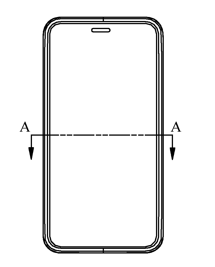
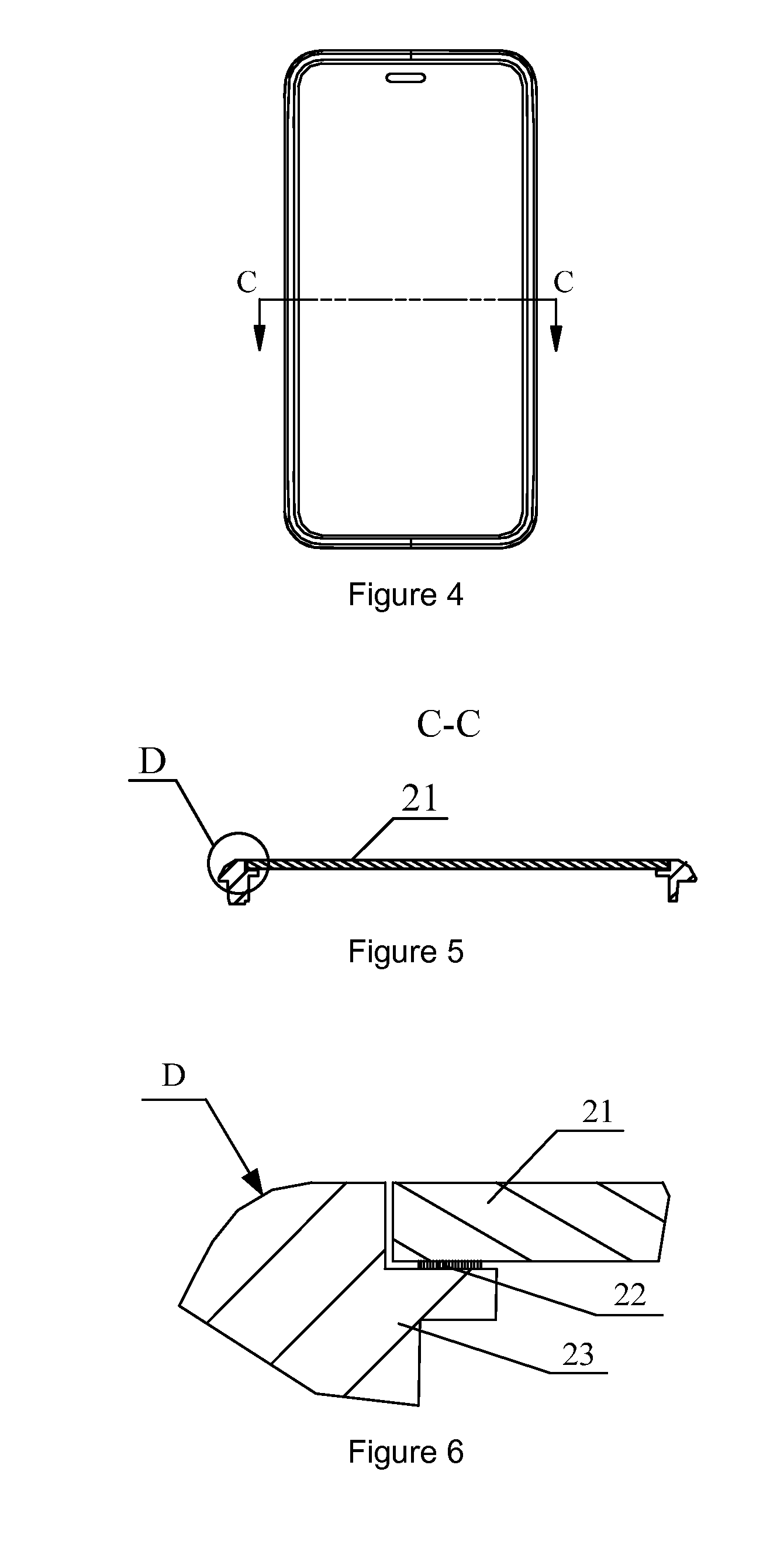
Handheld mobile device casing and molding method of the same

Inactive Publication Date: 2013-03-21
BALDA SOLUTION BEIJING
View PDF19 Cites 10 Cited by
  • Summary
  • Abstract
  • Description
  • Claims
  • Application Information

AI Technical Summary

Benefits of technology

[0010]In view of the above drawback in the existing handheld mobile device casings, the present invention provides a handheld mobile device casing that is

Problems solved by technology

cess. Such a sight window has unsatisfactory hardness and transparency, is easy to wear out, and is not durable e
b>. Though such a sight window is c

Method used


Image

  • Handheld mobile device casing and molding method of the same
  • Handheld mobile device casing and molding method of the same
  • Handheld mobile device casing and molding method of the same

Examples


Example

[0041]FIG. 8 is a schematic structural diagram of a first embodiment of the glass part in the present invention. In that step, the glass part is manufactured in a way that the side walls are made into straight wall structures, as shown in FIG. 8, which is to say, the side walls of the glass part are perpendicular to the top surface and bottom surface of the glass part.

Example

[0042]FIG. 9 is a schematic structural diagram of a second embodiment of the glass part in the present invention. In that step, the side walls of the glass part are made into skirt structures. As shown in FIG. 9, the side wall in skirt structure comprises a first flat section a, a second flat section b, and a cambered section c, wherein, one end of the second flat section b is connected to the first flat section a, and the other end of the second flat section b is tangent to the cambered section c. One end of the first flat section a is connected to the second flat section b, and the other end of the first flat section a is connected to the bottom surface of the glass part. One end of the cambered second c is tangent to the second flat section b, and the other end of the cambered section c is connected to the top surface of the glass part. The degree of inclination of the first flat section a is 70°˜90°, and the length of the first flat section a along the inclined direction is 0.4 ...

Example

[0052]FIG. 12 is a schematic structural diagram of a third embodiment of the handheld mobile device casing in the present invention. As shown in FIG. 12, in this embodiment, the supporting part 403 is a flat plate, there is an adhesive layer 402 between the glass sight window 401 and the supporting part 403. The dimension a3 of the glass sight window 401 is 0.3 mm˜0.7 mm, the dimension b3 of the supporting part 403 is greater than or equal to 0.3 mm, the dimension c3 of the supporting part 403 is 1.0 mm˜3.0 mm, and the dimension d3 of the casing 404 and partial glass sight window 401 is greater than or equal to 3.2 mm.

[0053]While the present invention is described above in some preferred embodiments, the present invention is not limited to those preferred embodiments. Any modification, equivalent replacement, and improvement made without departing from the spirit and principle of the present invention shall be deemed as falling into the protected domain of the present invention.


PUM

PropertyMeasurementUnit
Lengthaaaaaaaaaa
Lengthaaaaaaaaaa
Lengthaaaaaaaaaa

Abstract

A handheld mobile device casing and a molding method of the same includes manufacturing a glass part and a supporting part. The glass part is used as a sight window on the handheld mobile device casing, and the supporting part is used to support the glass part. The glass part is placed on the supporting part in a staggered manner, which is to say, one end of the supporting part is exposed out of the glass part. The injection molding is performed to form a handheld mobile device casing that encapsulates the glass part and supporting part. With that molding method, the boundary of the sight window can be tightly coupled to the casing, without any offset or clearance. The glass sight window has high hardness and is wear resistant. The molding process is easy to operate, and the subsequent assembly process can be simplified.

Description

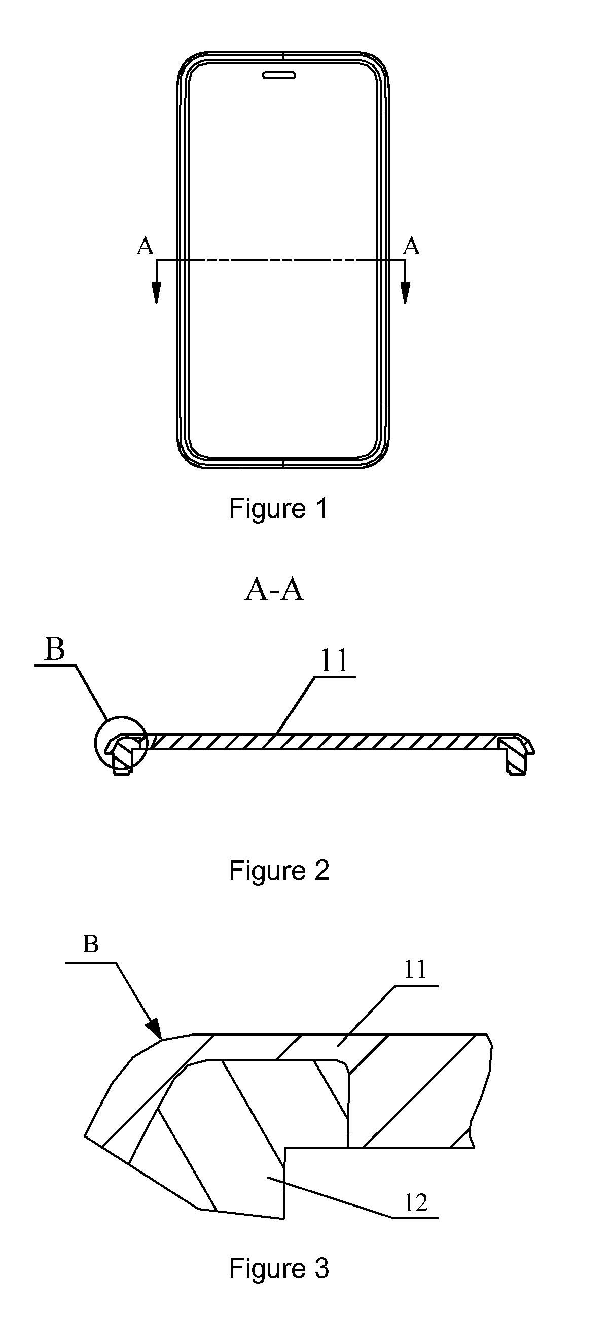
RELATED U.S. APPLICATIONS[0001]Not applicable.STATEMENT REGARDING FEDERALLY SPONSORED RESEARCH OR DEVELOPMENT[0002]Not applicable.REFERENCE TO MICROFICHE APPENDIX[0003]Not applicable.BACKGROUND OF THE INVENTION[0004]1. Field of the Invention[0005]The present invention relates to a casing and a molding method, in particular to a handheld mobile device casing and a molding method of the handheld mobile device casing.[0006]2. Description of Related Art[0007]Including Information Disclosed Under 37 CFR 1.97 and 37 CFR 1.98.[0008]The existing handheld mobile device casings can be manufactured into integral assemblies with a transparent sight window by means of a bi-color injection technique. FIG. 1 is a schematic structural diagram (1) of a handheld mobile device casing in the prior art. FIG. 2 is a sectional view in A-A direction of the handheld mobile device casing shown in FIG. 1. FIG. 3 is an enlarged view of the structure of part B in FIG. 2. As shown in FIGS. 1, 2, and 3, a transpa...

Claims


Application Information

Patent Timeline
IPC IPC(8): H05K5/03H05K13/00
CPCB29C45/14467B29K2709/08H05K5/03B29C45/14434H04M1/0266B29L2031/3481B29L2031/3437H05K13/00
Inventor HU, WEILINZHENG, WEI
Owner BALDA SOLUTION BEIJING
Why Eureka
Try Eureka