Display device, projector, and display method

a technology of display device and projector, applied in the field of display device, projector, display method, can solve the problems of large workload, complex calculation of data, and difficult preparation of data indicating relationships, so as to reduce the frequency of calibration

Active Publication Date: 2013-03-21
SEIKO EPSON CORP
View PDF5 Cites 27 Cited by
  • Summary
  • Abstract
  • Description
  • Claims
  • Application Information

AI Technical Summary

Benefits of technology

[0027]According to the aspects of the invention, the coordinates of the pointed location with respect to the display image displayed on the display surface may be output as t

Problems solved by technology

Generally, it is necessary to recalibrate at each time when the display condition changes in such a way that the display location of the displayed image changes, and lots of effort is required.
There are a wide variety of changes of display conditions in the display device, and it is not easy to prepare data indicating relationships between before and after the changes in

Method used


Image

  • Display device, projector, and display method
  • Display device, projector, and display method
  • Display device, projector, and display method

Examples


Embodiment Construction

[0039]As below, embodiments to which the invention is applied will be explained with reference to the drawings.

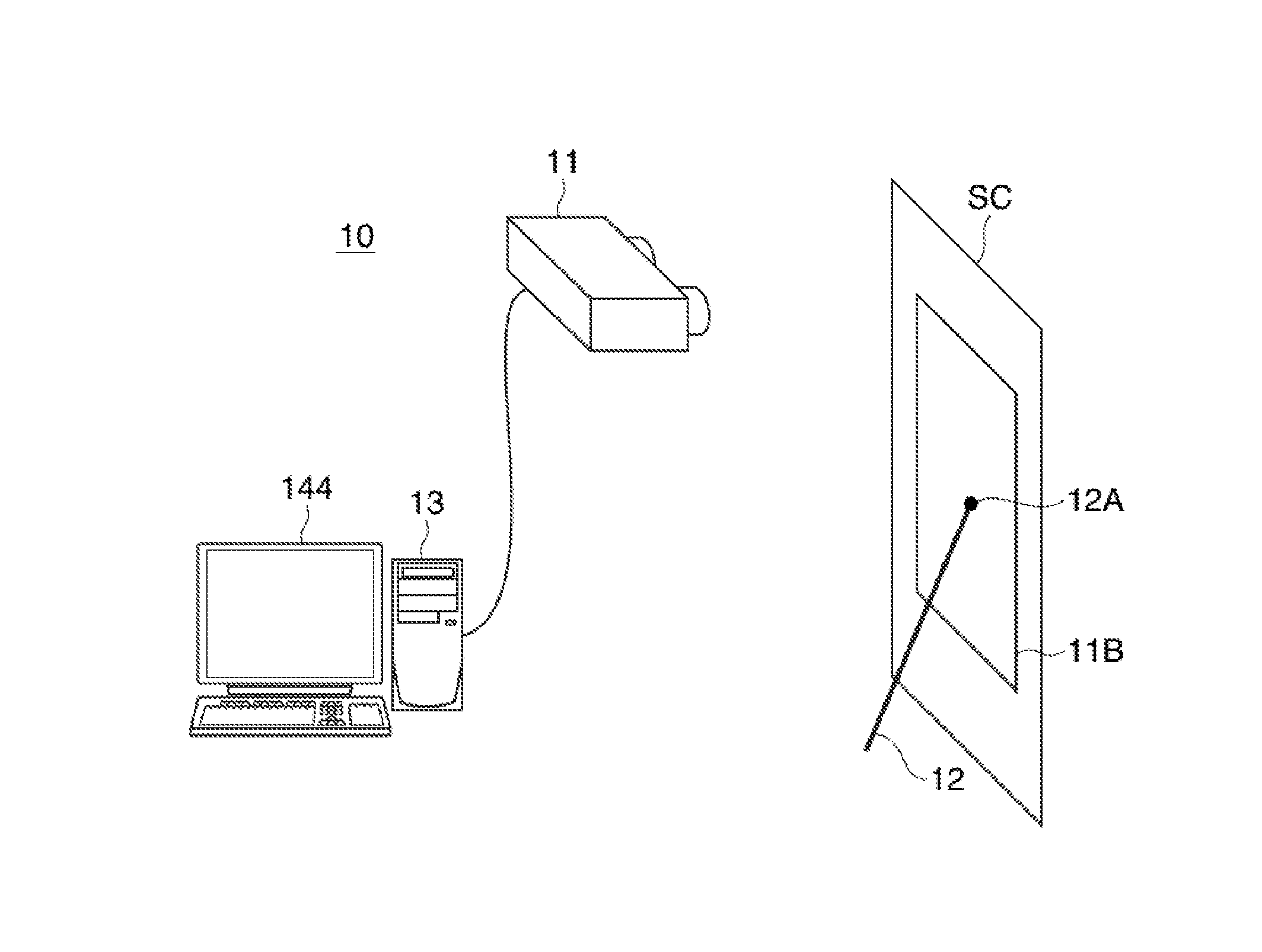
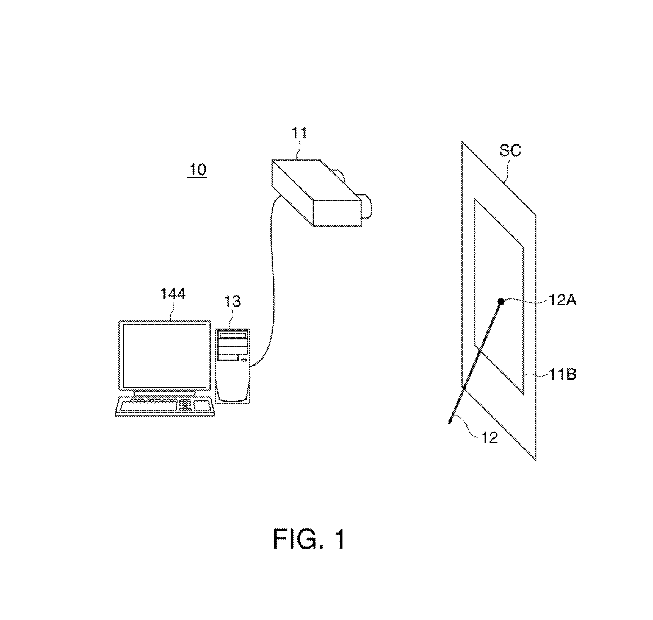
[0040]FIG. 1 shows a configuration of a display system 10 using a projector 11 according to an embodiment.

[0041]The projector 11 as a display device is wired-connected to a PC (Personal Computer) 13 as an image supply device by an image signal cable or the like. Image data is input from the PC 13 to the projector 11, and the projector 11 projects a display image on a screen SC as a projection surface (display surface) based on the input image data. Further, the projector 11 is connected to the PC 13 by a communication cable or the like and transmits and receives control data etc. between the PC 13 and itself. The projector 11 may perform projection if the image data input from the PC 13 represents a still image or a moving image. The screen SC is not limited to a flat plate fixed to a wall surface, but the wall surface itself may be used as the screen SC. Here, a range in w...


PUM


Abstract

A display device include a display unit that displays a display image on a display surface based on image data, a location detection unit that detects a pointed location with respect to the display image on the display surface, a coordinate calculation unit that calculates first coordinates as coordinates of the pointed location in a displayable area within the display surface, a coordinate conversion unit that converts the first coordinates calculated by the coordinate calculation unit into second coordinates as coordinates in the image data, and an output unit that outputs the second coordinates obtained by the coordinate conversion unit.

Description

BACKGROUND[0001]1. Technical Field[0002]The present invention relates to a display device that outputs information of a pointed location, a projector, and a display method.[0003]2. Related Art[0004]In related art, when a specific location of an image displayed by a display device such as a projector is pointed, a device of detecting the pointed location and displaying a pointer or the like in response to the detected location has been known (for example, see Patent Document 1 (Japanese Patent No. 4272904)). In this type of device, it is necessary to perform calibration so that the pointed location and the display location of the pointer or the like may coincide with each other. Generally, it is necessary to recalibrate at each time when the display condition changes in such a way that the display location of the displayed image changes, and lots of effort is required. Accordingly, in the device disclosed in Patent Document 1, when the display location changes, location change data i...

Claims


Application Information

Patent Timeline
IPC IPC(8): G06F3/033
CPCG06F3/033G06F3/03545G06F3/0418G06F3/0425
Inventor ICHIEDA, HIROYUKI
Owner SEIKO EPSON CORP
Why Eureka
Try Eureka