
Method for Controlling a Measuring System and Measuring System for Implementing the Method

a technology of measuring system and measuring system, which is applied in the direction of speed measurement using acceleration, color television, television system, etc., can solve the problems of increasing the memory requirement of the evaluation device, increasing the energy consumption, and difficult to operate the sensor by battery, so as to achieve the effect of less energy consumption

Active Publication Date: 2013-03-21
BEISSBARTH AUTOMOTIVE TESTING SOLUTIONS GMBH
View PDF3 Cites 8 Cited by
  • Summary
  • Abstract
  • Description
  • Claims
  • Application Information

AI Technical Summary

Benefits of technology

The patent describes a method for measuring vehicles using a measuring system with two detectors and image acquiring devices. The detectors are calibrated using a signal from a first detector and image acquisition is started in the opposite detectors. This reduces energy requirements and processor load. Another advantage is that when a vehicle breaks a light barrier, the measurement is ended, so no unnecessary computer capacity, energy consumption, or processing load is required.

Problems solved by technology

This creates a high demand for the illumination of the object to be measured and for the computing power of the measuring device and an evaluation unit, which means an increased energy consumption and makes it difficult to operate the sensor by battery.
Since the wheel detection and wheel measurement algorithms normally differ, the pictures taken for wheel detection must be stored temporarily in order to be able to be used for wheel measurement as well, which in the known methods also results in an increased memory requirement in the evaluation device.

Method used


Image

  • Method for Controlling a Measuring System and Measuring System for Implementing the Method
  • Method for Controlling a Measuring System and Measuring System for Implementing the Method

Examples


Embodiment Construction

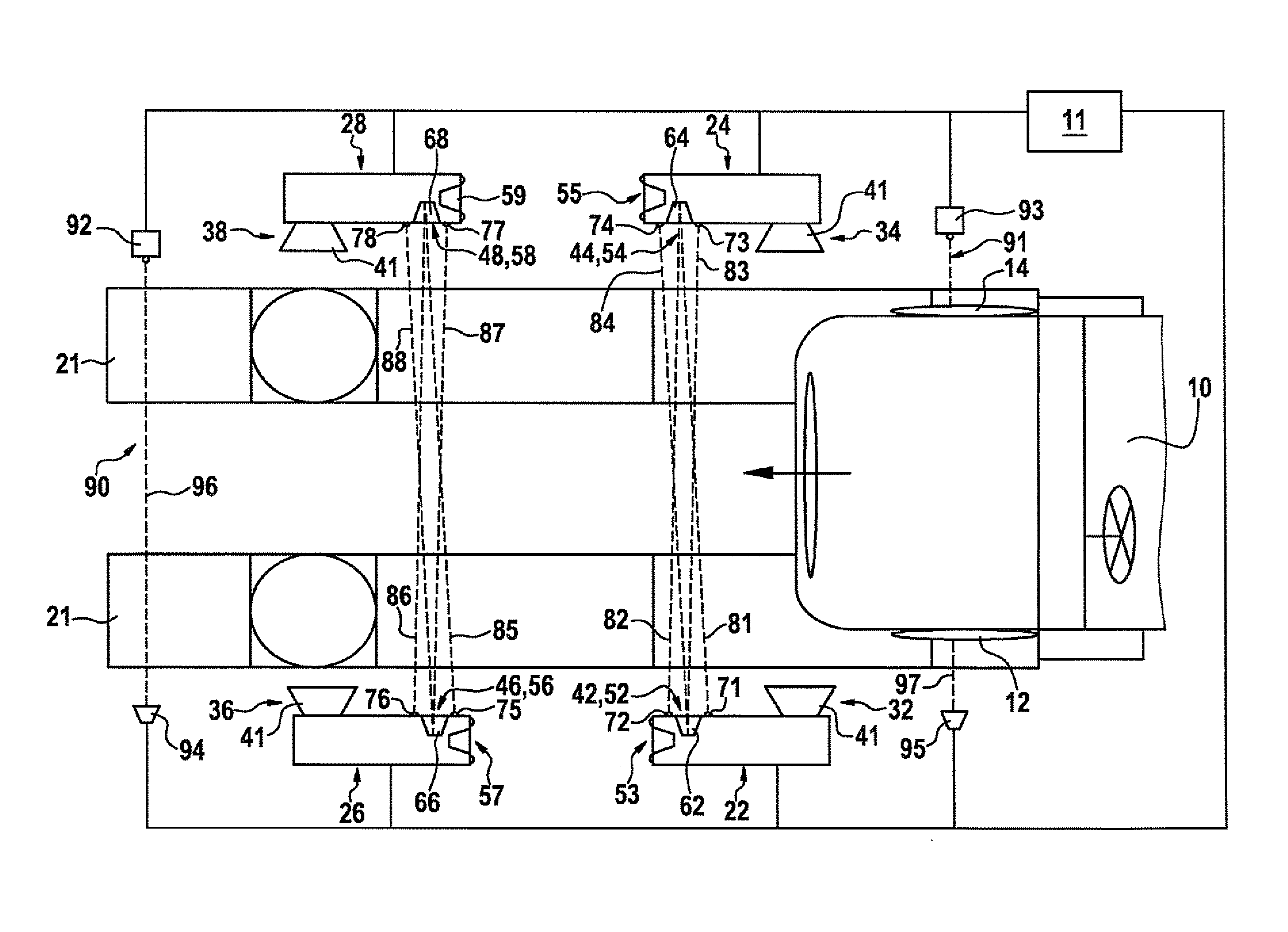
[0018]The represented measuring station shows a motor vehicle 10, which is situated in the measuring station so that its chassis may be measured. Motor vehicle 10 has a front left wheel 12, a front right wheel 14, and a rear left wheel and a rear right wheel, which are not shown in the FIGURE.

[0019]The measuring station has two elongated tire contact areas 21 having rotating and sliding plates as contact areas for front wheels 12, 14 and for the rear wheels (not shown). These elongated tire contact areas 21 are developed as travel rails in the case of lifting platforms, and as drive-up areas in the case of repair shop pits.

[0020]Four measuring devices 22, 24, 26, 28 are positioned on the measuring station, measuring device 22 being used for the rear left wheel, measuring device 24 being used for the rear right wheel, measuring device 26 being used for the front left wheel 12 and measuring device 28 being used for the front right wheel 14. Measuring devices 22, 24, 26, 28 respectivel...


PUM


Abstract

In a method for controlling a measuring system in a chassis measuring station, the motor vehicle is detected automatically in the measuring station by at least one detection unit and its position is ascertained with respect to at least one measuring device which is controlled on the basis of a signal of the detection unit in that an operating state of the measuring device is activated. The measuring system includes at least two mutually opposite measuring devices, which respectively have one image acquisition unit and one transverse referencing unit, and at least one detection unit, which is a light barrier having at least one transmitter and receiver.

Description

BACKGROUND OF THE INVENTION[0001]1. Field of the Invention[0002]The present invention relates to a method for controlling a measuring system on a measuring station of a chassis measuring facility or a motor vehicle inspection line and to a measuring system for implementing the method.[0003]2. Description of the Related Art[0004]A method for the relative positioning of an object to be measured and a motor vehicle with respect to a measuring device is already known from published German patent application document DE 10 2006 041 821 A1. In this method, the object to be measured is first detected by the measuring device and the position of the object to be measured with respect to the measuring device is ascertained. Then a feedback signal is generated which indicates whether the object to be measured is located in a position that is suitable for taking the measurement or not. Additional feedback signals make it possible to bring the object to be measured into a position that is suitab...

Claims


Application Information

Patent Timeline
IPC IPC(8): H04N7/18G01P3/00G06F15/00
CPCG01B11/275G01B2210/143G01B2210/12
Inventor SEIFERT, WOLFGANG
Owner BEISSBARTH AUTOMOTIVE TESTING SOLUTIONS GMBH
Learn More