
Laser spot tracking with off-axis angle detection

Active Publication Date: 2013-03-21
ANALOG MODULES
View PDF5 Cites 94 Cited by
  • Summary
  • Abstract
  • Description
  • Claims
  • Application Information

AI Technical Summary

Benefits of technology

The patent describes a system called SPOTTR that helps a operator quickly and accurately target a specific target using a laser designator. The system uses a quadrant detector to confirm the code and location of the target, and a laser designator to illuminate the target and make it easier for the operator to see. This saves time and reduces errors, which can help prevent friendly fire or collateral damage. The system also allows the operator to target multiple targets without having to move the reticule to a specific position for each target. Overall, the system improves targeting accuracy and efficiency.

Problems solved by technology

While LGWs are highly accurate under ideal conditions, they present a number of challenges to be used successfully, making them somewhat less than the “silver bullet” sometimes suggested.
The first problem is designation.
If the designator's “sparkle” is turned off, blocked, or moved, the weapon's accuracy will be greatly reduced.
Laser designation is also very vulnerable to weather conditions.
Cloud cover, rain, and smoke frequently make reliable designation impossible.
One problem with LGWs is that there may be false returns from other than the desired target, such as from a nearby sand dune or vehicle.
And, in some cases, mistakes are made and the wrong target can be attacked with potentially severe consequences.
It has very short range and because it essentially collects and integrates the light from the scene, it cannot decode the pulse timing.
However, ground LDOs normally have more powerful optics to acquire targets, more time, and lower task loading than do aircrews of fighter or attack aircraft.
However, lower code numbers cause faster battery drain.
An input resistor is chosen for the amplifier such that its resistance value is much greater than the input impedance of the first amplifier, resulting in insignificant change in input impedance when the first amplifier's output becomes saturated.

Method used


Image

  • Laser spot tracking with off-axis angle detection
  • Laser spot tracking with off-axis angle detection
  • Laser spot tracking with off-axis angle detection

Examples


Embodiment Construction

[0145]The subject matter of the parent application (Ser. No. 11 / 423,367 filed Jun. 9, 2006) is generally directed to a device (Stabilized Portable Optical Target Tracking Receiver; referred to herein as “SPOTTR”) for spotting reflections from lasers illuminating targets, including decoding and displaying laser codes, and to deploying the device in a battlefield scenario.

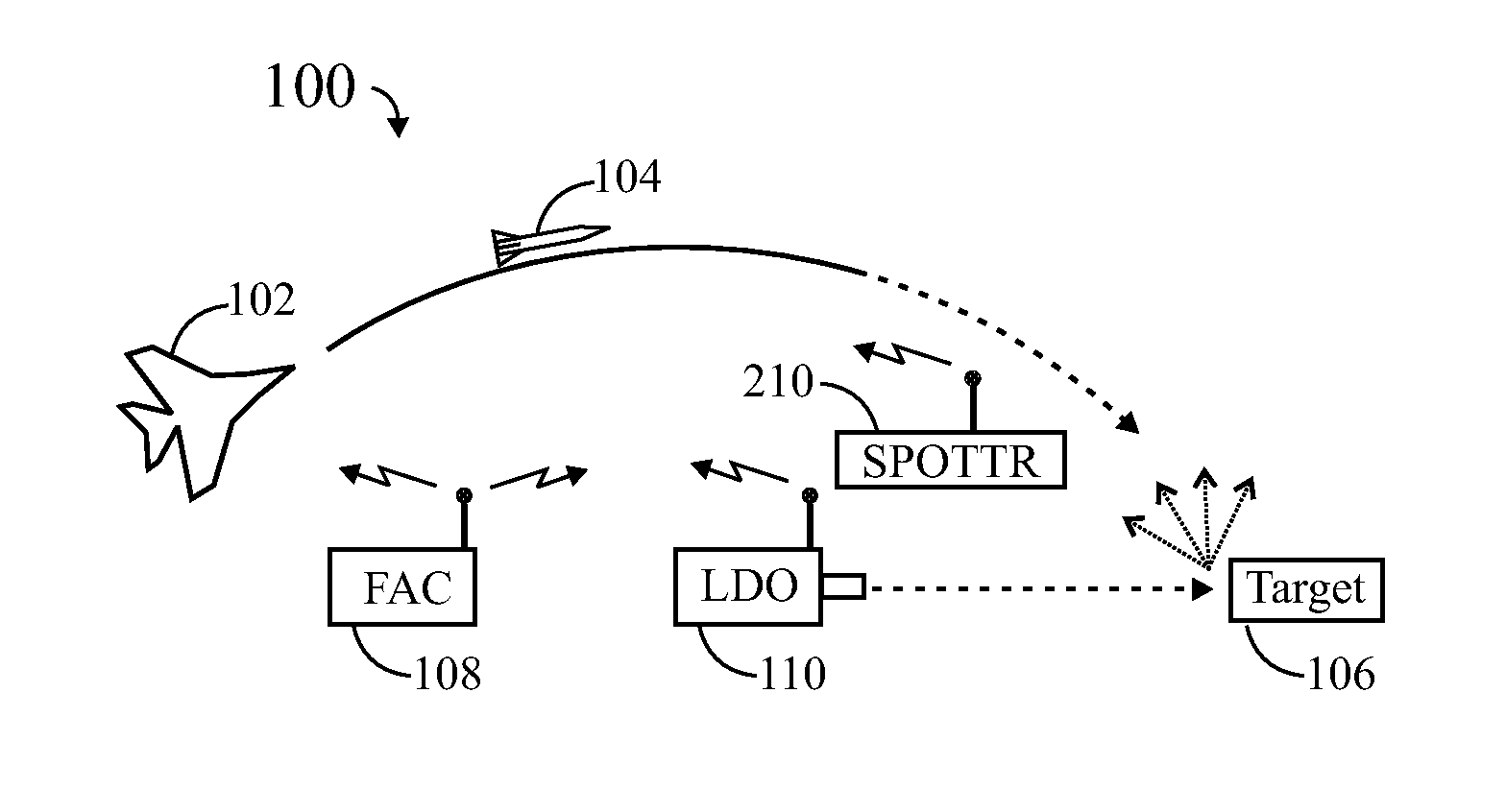
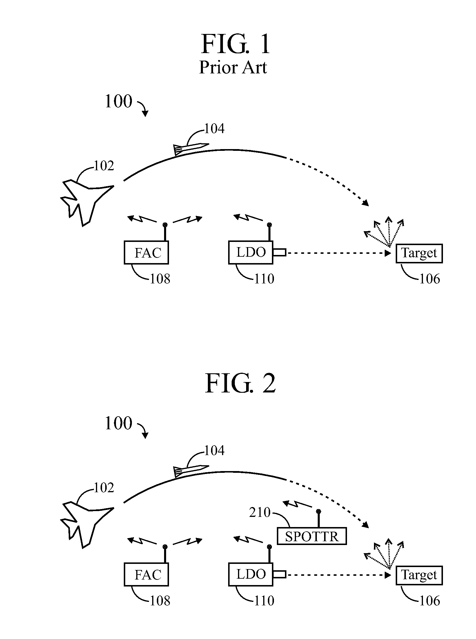
[0146]FIG. 2 shows a target tracking receiver 210 deployed in the battlefield scenario 100 of FIG. 1.

[0147]The target tracking receiver (SPOTTR) 210 can provide accurate stand-off verification of target illumination by airborne or ground laser designators (110). This object may be achieved by use of a Stabilized Portable Optical Target Tracking Receiver (SPOTTR).

[0148]SPOTTR is designed to allow an operator (Joint Terminal Attack Controller (JTAC)) on the ground near the target area, to detect and decode laser energy from an airborne or ground laser designating military targets. SPOTTR greatly increases the assurance...


PUM


Abstract

A laser spot tracker comprising a quadrant detector. A portion of a spot of laser light reflected from an object being illuminated (OBI) may be defocused to occupy a significant portion such as one-third of the field of view, while another portion remains focused, therefore allowing for quick calculation of the spot centroid. With such a “composite spot”, multiple target (OBI) positions may simultaneously be defined in elevation and azimuth with respect to null by analyzing the energy in each quadrant. The X and Y angle information (off null) for multiple targets (OBIs), and their codes may be displayed. For a large, defocused spot, two segmented multi-element detectors may be used, one in front of and the other behind the focal plane to reduce the effects of hot spots in a spot of laser light collected from an object being illuminated.

Description

CROSS-REFERENCE TO RELATED APPLICATIONS[0001]This is a continuation-in-part of Ser. No. 11 / 423,367 filed Jun. 9, 2006, which is a non-provisional filing of provisional 60 / 688,962 filed Jun. 9, 2005.TECHNICAL FIELD[0002]The invention relates generally to laser-guided weapon (LGW) systems and, more particularly, to optical receivers for LGW systems.BACKGROUND[0003]Laser-guided munitions (generally referred to as laser-guided bombs (LGBs), laser guided weapon systems (such as in an aircraft), or laser-guided weapons (LGWs) use a laser designator to mark (illuminate, “paint”) a target. The reflected laser light (“sparkle”) from the target is then detected by the seeker head of the weapon, which sends signals to the weapon's control surfaces (fins) to guide it toward the designated point. The illuminating laser light is encoded, and the laser receiver in the LGW is set to react only to reflected laser light having the proper code.[0004]An extensive discussion of laser designation techniq...

Claims


Application Information

Patent Timeline
IPC IPC(8): G01S17/66
CPCG01S17/66G01C3/08G01S3/784F41G7/2293G01S3/781F41G7/226F41G3/145
Inventor CRAWFORD, IAN D.CHANDLER, NOALHARWICK, JOHNWILDON, DWIGHTSMITH, CHARLES G.
Owner ANALOG MODULES
Learn More