Connector and connector assembly

a technology of connectors and connectors, applied in the direction of packaging foodstuffs, packaged goods types, pharmaceutical containers, etc., can solve the problems of not being able to feed the solution with safety and certainty, and achieve the effect of preventing the inadvertent separation of medical devices

Inactive Publication Date: 2013-03-21
TERUMO KK
View PDF14 Cites 52 Cited by
  • Summary
  • Abstract
  • Description
  • Claims
  • Application Information

AI Technical Summary

Benefits of technology

[0008]The object of the present invention contemplates provision of a connector and a connector assembly wherein inadvertent separation of a medical device can be prevented.

Problems solved by technology

However, the conventional connector assembly has a drawback that, if the syringe or the lock adapter is rotated in a direction in which the screwing engagement is loosened, then it is separated simply.
Therefore, there is the possibility that the solution may not be fed with safely and certainty through the connector assembly.

Method used


Image

  • Connector and connector assembly
  • Connector and connector assembly
  • Connector and connector assembly

Examples


Embodiment Construction

[0050]In the following, a connector and a connector assembly of the present invention are described in detail based on a preferred embodiment shown in the accompanying drawings.

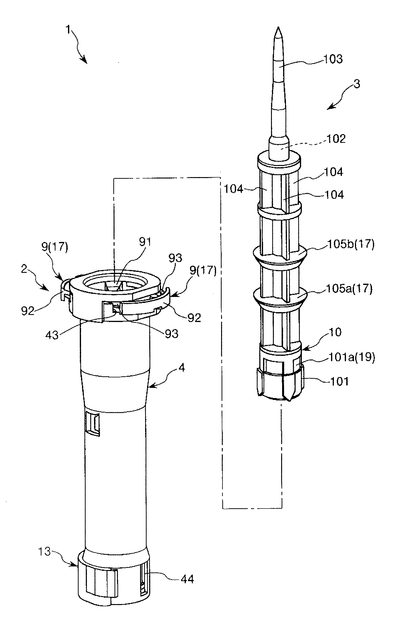
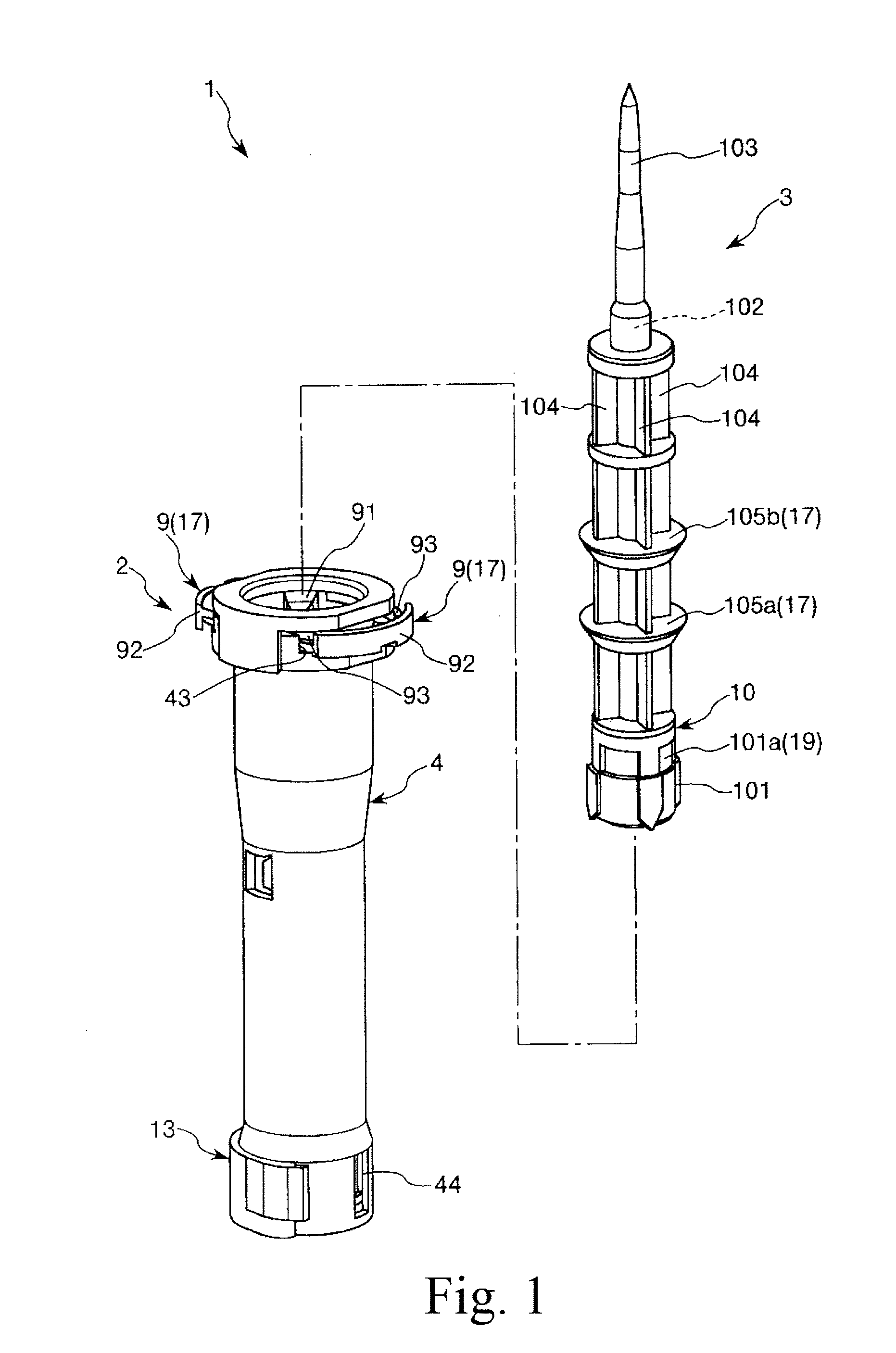
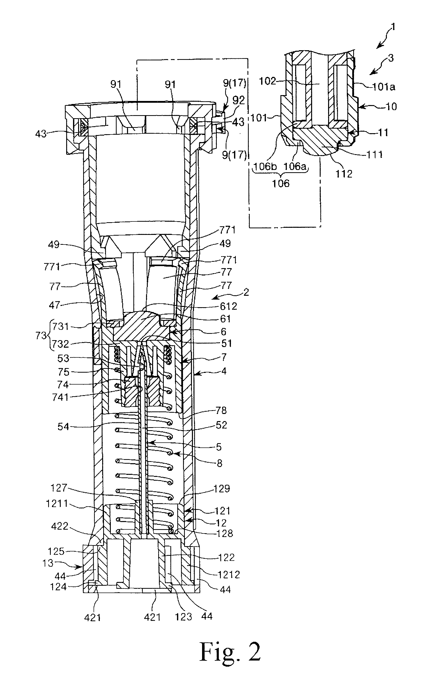
[0051]FIG. 1 is an exploded perspective view showing an embodiment of a connector assembly of the present invention; FIGS. 2 to 5 are vertical sectional views illustrating a process until a first connector and a second connector of the connector assembly shown in FIG. 1 are placed into an assembled state; FIGS. 6 to 9 are perspective views illustrating a process until the first connector and the second connector of the connector assembly shown in FIG. 1 are placed into the assembled state (views corresponding to FIGS. 2 to 5, respectively); FIG. 10 is a sectional view taken along line A-A of FIG. 3; FIG. 11 is a sectional view taken along line B-B of FIG. 4; FIG. 12 is a perspective view showing elements in the proximity of a proximal end portion of the first connector of the connector assembly shown in FIG. ...


PUM


Abstract

A first connector includes a first connector main body configured from an outer tube of cylindrical shape, an inner tube of cylindrical shape, a hub disposed at a proximal end portion of the outer tube, and a clip disposed so as to be removable at the proximal end portion of the outer tube, a hollow needle supported on the hub, a first sealing member supported on the inner tube, a coil spring serving as puncturing portion biasing means for biasing the first sealing member toward the distal direction, and a clamping member disposed upon the outer tube. In a state in which the clip is mounted to the proximal end portion of the outer tube, a protrusion of the clip engages with a protrusion of the hub, and thereby rotation of the hub is prevented. If the clip is removed, the hub becomes rotatable with respect to the outer tube.

Description

TECHNICAL FIELD[0001]The present invention relates to a connector and a connector assembly.BACKGROUND ART[0002]Usually, a drug such as an anti-cancer agent or an immunosuppressive agent which is dangerous if a health care worker touches by mistake is accommodated in a state of powder in a vial container which is sealed at a mouth portion thereof with a rubber stopper.[0003]In order to take out the drug from such a vial container as just described, the following operations are carried out.[0004]First, the mouth portion of the vial container and a mouth portion of a syringe into which liquid for dissolving has been dealt out are connected to each other through a connector assembly configured from a first connector and a second connector. In this instance, a lock adapter having screw threads formed on an inner circumferential face thereof is provided on an outer circumferential portion of the mouth portion of the syringe (refer to, for example, Patent Document 1), and when the syringe ...

Claims


Application Information

Patent Timeline
Patent Type & Authority Applications(United States)
IPC IPC(8): A61J1/20
CPCA61J1/1475A61J1/2096A61M2039/1072A61M39/1011A61M2039/1033A61J2001/201A61J1/201
Inventor TAKEMOTO, MASAFUMI
Owner TERUMO KK
Why Eureka
Try Eureka