Heating device
a heating device and heat sink technology, applied in the direction of contraceptive devices, metal working devices, manufacturing tools, etc., can solve the problems of inability to receive a sufficient heating effect, inability to contact the exothermic composition inside the chemical warmer with air, and difficulty in contacting the exothermic composition with air, etc., to achieve the effect of stably imparting a heating effect to the affected area, not easily shifted, and advantageously imparting moisturizing effects
Inactive Publication Date: 2013-03-21
KOBAYASHI PHARMA CO LTD
View PDF17 Cites 3 Cited by
- Summary
- Abstract
- Description
- Claims
- Application Information
AI Technical Summary
Benefits of technology
The heating device in this patent allows for stable heating and moisturizing effects for many hours. It is designed to come into contact with the body, and cannot easily shift from the affected area due to movement or contact with objects. It also ensures uniform heating and moisturizing effects throughout the heat-generating portion, regardless of which part is covered. This design overcomes the drawbacks of known heating devices that may result in non-uniform effects.
Problems solved by technology
In such cases, the area to be treated or rehabilitated may not be able to receive a sufficient heating effect.
This cold protection device (muffler) is used around the neck, and thus does not easily shift from the position being warmed.
However, when the cold protection device (muffler) of Patent Document 3 is used around the neck, the outer side of the chemical warmer (i.e., the face not in contact with the body) is covered with the cloth; therefore, the exothermic composition inside the chemical warmer cannot be sufficiently contacted with air.
Moreover, the muffler is usually wound in layers when it is used, making the contact of the exothermic composition with air even more difficult.
For this reason, the muffler may not provide a desired heating effect because of insufficient heat generation of the chemical warmer inside the muffler.
Method used
View moreImage
Smart ImageViewing Examples
Examples
examples
[0127]Referring to the following Examples and Comparative Examples, the invention is described in greater detail below; however, the invention is not limited to these Examples.
Login to View More PUM
| Property | Measurement | Unit |
|---|---|---|
| length | aaaaa | aaaaa |
| length | aaaaa | aaaaa |
| width | aaaaa | aaaaa |
Abstract
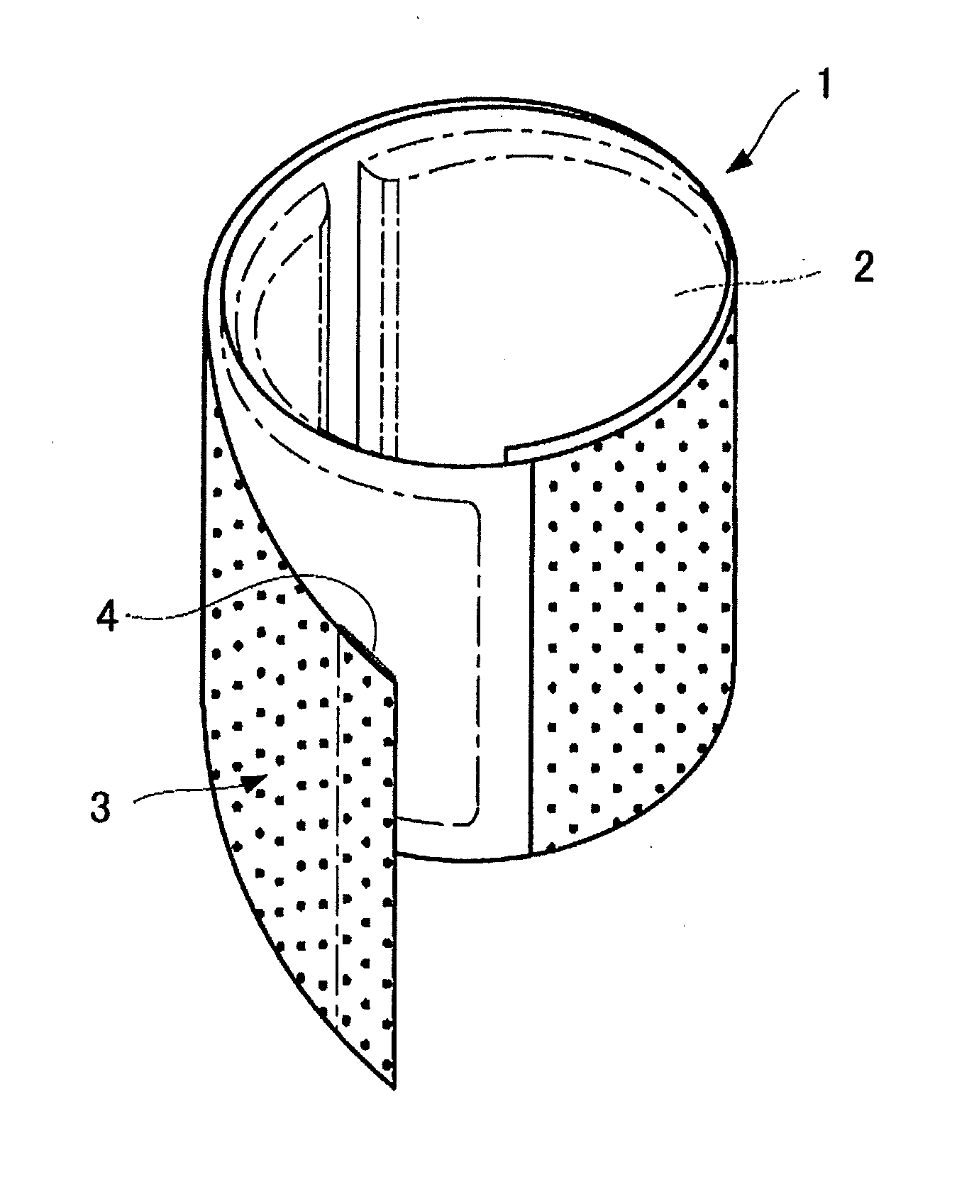
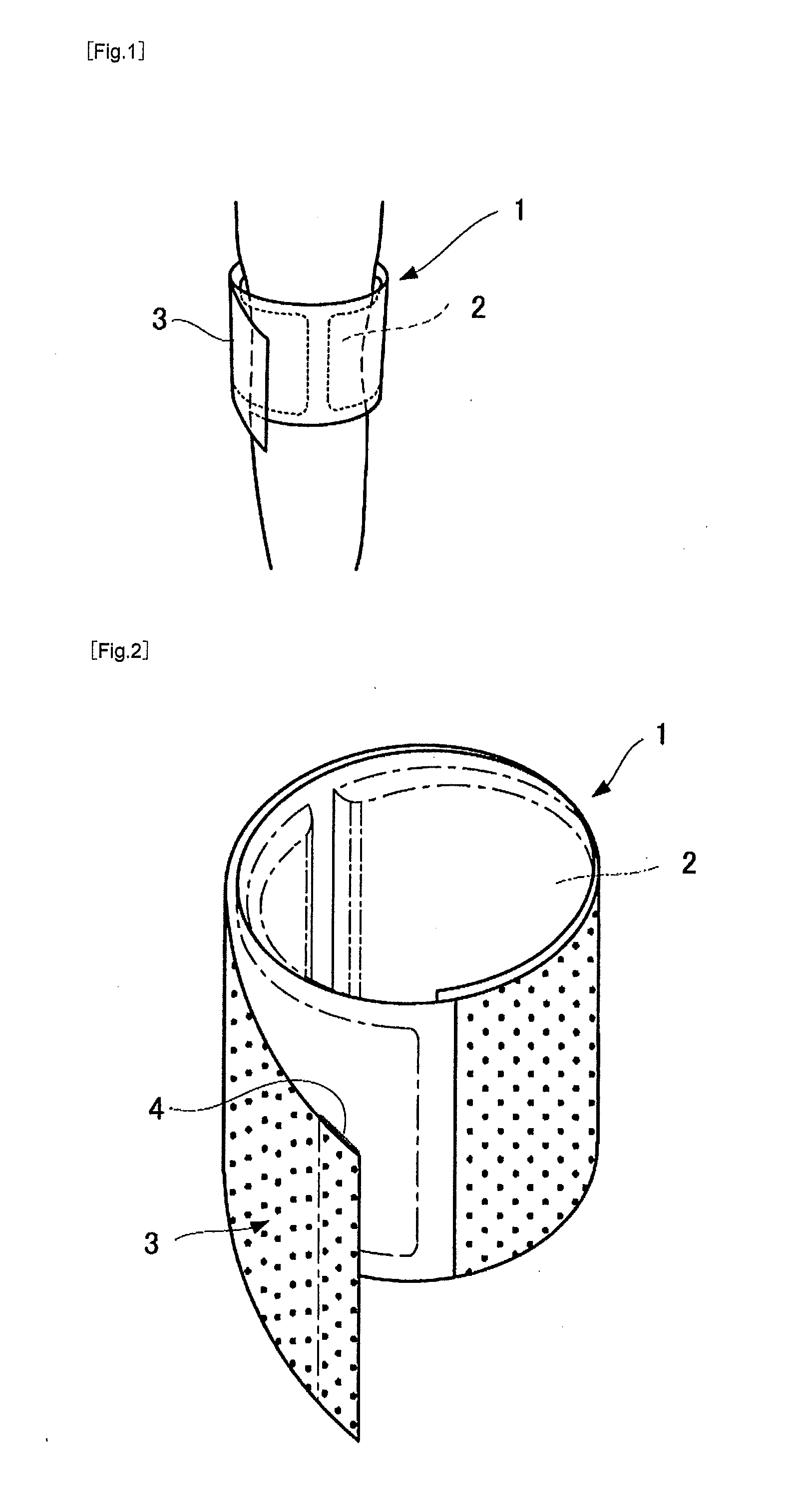
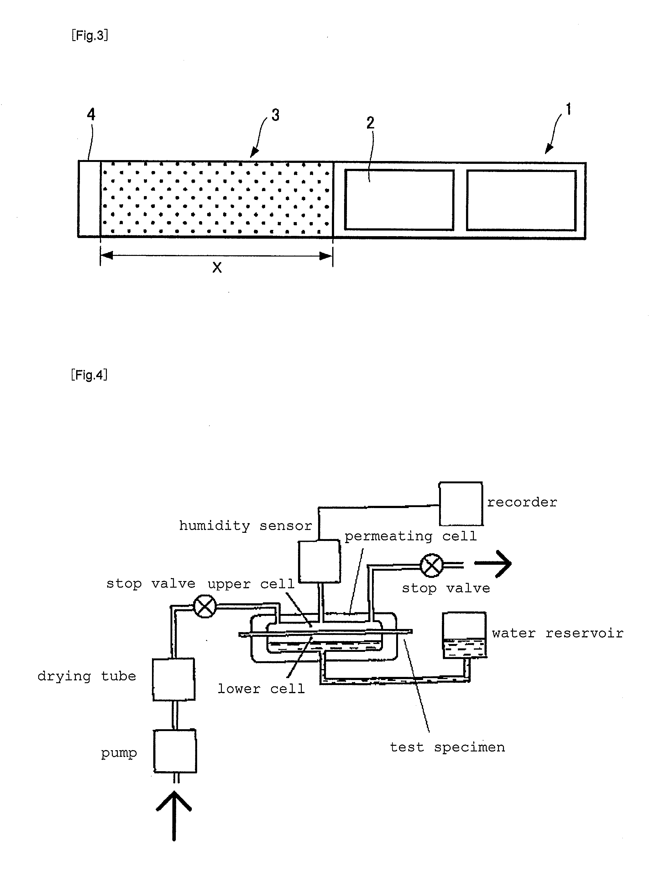
An object of the invention is to provide a heating device that is securely held in its worn position, and that can exhibit a sufficient heating effect.A heating device comprising:a heat-generating portion having an exothermic composition enclosed in one or more sections, the exothermic composition generating heat by contact with air; andan elastic band portion;(1) the band portion surrounding all or a portion of the heat-generating portion to keep the heat-generating portion in contact with the body;(2) the band portion being connected to an end of the heat-generating portion;(3) a face of the heat-generating portion that is brought into contact with the band portion having a moisture permeability of 340 to 610 g / m2 per day, as measured according to Method A (Humidity Sensor Method) defined in JIS K7129; and(4) the band portion having an air permeability of 3 s / 300 cc to 61 s / 300 cc, as measured according to JIS P 8117-1998: “Paper and board—Determination of air permeance and air resistance: Gurley method”.
Description
TECHNICAL FIELD[0001]The present invention relates to heating devices, and, in particular, to therapeutic or rehabilitation devices for the wrist, ankle, knee, elbow, or neck.BACKGROUND ART[0002]Heating devices with a heat-generating portion have been previously proposed as therapeutic or rehabilitation devices. Such heating devices generate heat when an exothermic composition inside the heat-generating portion comes into contact with air, thereby imparting a heating effect to an affected area.[0003]For example, Patent Documents 1 and 2 disclose heating devices in the form of cylindrical supporters holding a chemical warmer. These supporters are worn on an affected area, such as the wrist or ankle, and impart a heating effect to the affected area by the heat generation of the chemical warmer.[0004]However, when the supporters of Patent Documents 1 and are worn for many hours, they may be shifted from their original positions by, for example, the movement of the wearer or by contact ...
Claims
Login to View More Application Information
Patent Timeline
 Patent Type & Authority Applications(United States)
IPC IPC(8): A61F7/03B23P25/00
CPCA61F7/02A61F7/034Y10T29/49982A61F2007/0258A61F2007/0228
Inventor MATSUO, ATSUSHI
Owner KOBAYASHI PHARMA CO LTD
Features
- R&D
- Intellectual Property
- Life Sciences
- Materials
- Tech Scout
- Unparalleled Data Quality
- Higher Quality Content
- 60% Fewer Hallucinations
Learn More Browse by: Latest US Patents, China's latest patents, Technical Efficacy Thesaurus, Application Domain, Technology Topic, Popular Technical Reports.
© 2025 PatSnap. All rights reserved.Legal|Privacy policy|Modern Slavery Act Transparency Statement|Sitemap|About US| Contact US: help@patsnap.com


