Printer

a printing machine and printing plate technology, applied in the field of printing machines, can solve the problems of printing unevenness, printing unevenness, printing unevenness, etc., and achieve the effects of reducing or preventing the reduction of printing quality due to the electric charge of the medium, reducing or preventing the reduction of printing quality, and reducing or preventing the reduction of printing unevenness

Inactive Publication Date: 2020-03-19
ROLAND DG CORP
View PDF3 Cites 0 Cited by
  • Summary
  • Abstract
  • Description
  • Claims
  • Application Information

AI Technical Summary

Benefits of technology

[0006]In view of the foregoing, preferred embodiments of the present invention provide printers that each decrease or prevent a reduction of printing quality.
[0008]For example, the ink that is discharged from the ink head has been electrically charged and electric charges have been generated in the ink. Also, the medium is electrically charged by rubbing with the platen when being conveyed, and therefore, electric charges are generated in the medium. However, for example, when the platen and the medium contact each other, electric charges of an opposite polarity to that of electric charges of the medium concentrate on a surface of the platen made of metal and a state in which the electric charges of the electrically charged medium and the electric charges of the surface of the platen are apparently coupled (in other words, an electrically neutralized state) is established. Thus, for a portion in which the platen and the medium contact each other, when the ink is discharged to the medium, the track of ink is hardly changed by the electric charges of the medium. However, when the medium floats up from the platen, a floating portion does not contact the platen. Therefore, for example, the electric charges that have been generated in the floating portion of the medium are not pulled by the electric charges of the platen and exist in the medium. Because of this, the electric charges easily exist also in an upper portion of the medium. The electric charges of the medium and the electric charges of the ink react to each other in the floating portion of the medium, and thereby, the track of the ink that has been discharged from the ink head is changed. As a result, printing unevenness occurs. Then, the present inventor discovered that electricity is removed from the medium before the ink is discharged, and thereby, the track of the ink is hardly shifted due to the electric charges of the medium.
[0010]In a printer according to a preferred embodiment of the present disclosure, the ink is discharged to the irradiated range of the medium which has been irradiated with the plasma, and thereby, printing is performed. In a portion of the medium on which printing has not been performed yet, electric charges exist in the medium but electric charges do not exist in the insulator, and therefore, over the insulator, the electric charges of the medium easily exist in an upper portion of the medium. In the above described state, a range of the medium located over the insulator is irradiated with plasma, and thereby, the electric charges in the range of the medium located over the insulator can be easily removed. Therefore, electric charges hardly exist in the irradiated range of the medium. In various preferred embodiments of the present disclosure, the ink is discharged to the irradiated range of the medium in which electric charges hardly exist, and therefore, the track of the ink is hardly shifted due to the electric charges of the medium. Accordingly, the occurrence of printing unevenness due to the electric charges of the medium is able to be reduced or prevented. As a result, reduction of printing quality due to the electric charges of the medium is able to be decreased or prevented.
[0011]According to preferred embodiments of the present disclosure, printers that are each able to decrease or prevent a reduction of printing quality are provided.

Problems solved by technology

As a result, printing unevenness occurs.
As a result, the present inventor discovered that electric charges are generated in each of the medium that moves relative to the platen during printing and the ink that is discharged from the ink head, a track of the ink is changed by the electric charges thus causing printing unevenness occurs.
As a result, printing unevenness occurs.

Method used


Image

  • Printer
  • Printer
  • Printer

Examples


Embodiment Construction

[0023]With reference to the attached drawings, printers according to preferred embodiments of the present disclosure will be described below. Note that, as a matter of course, preferred embodiments described herein are not intended to be particularly limiting of the present invention. Also, elements and portions that have the same function are denoted by the same reference character and redundant description will be omitted or simplified, as appropriate.

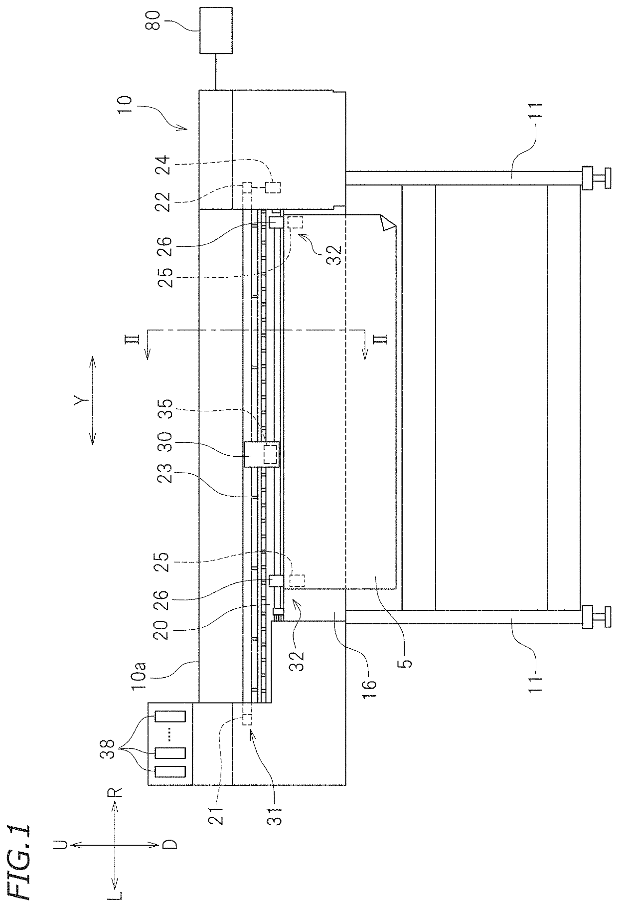
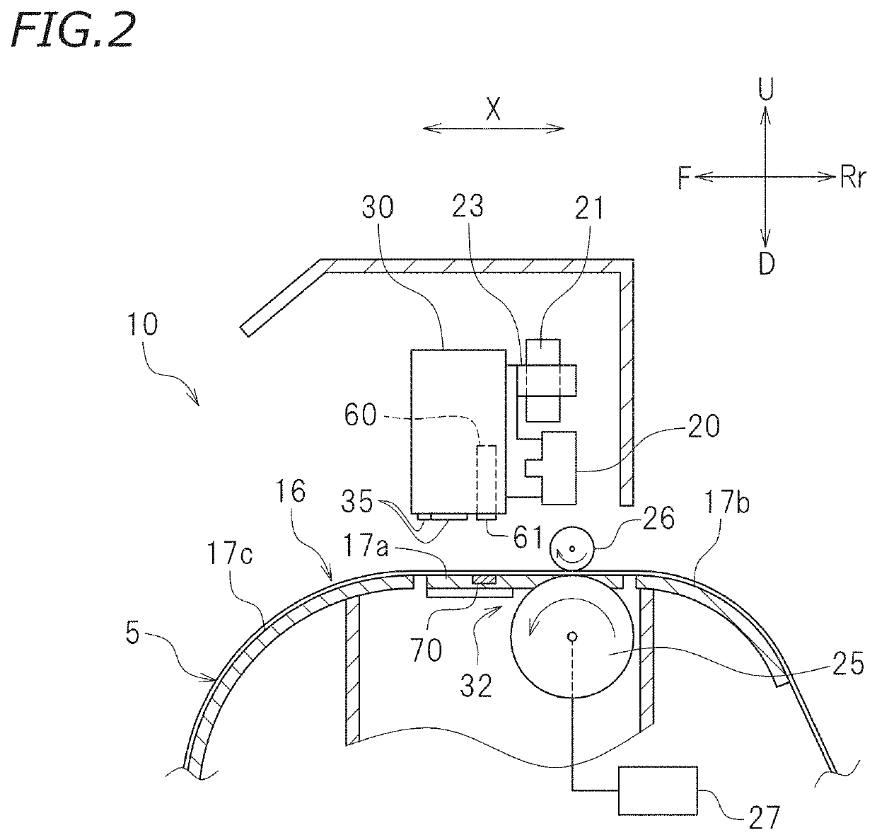
[0024]FIG. 1 is a front view of a printer 10 according to a preferred embodiment of the present invention. FIG. 2 is a cross-sectional view of the printer 10 taken along a line II-II of FIG. 1. In the following description, when a user views the printer 10 from front, a direction in which the user goes away from the printer 10 will be referred to as front and a direction in which the user approaches the printer 10 is referred to as rear. The terms left, right, up, and down refer to left, right, up, and down when the printer 10 is vie...


PUM

PropertyMeasurementUnit
depthaaaaaaaaaa
lengthaaaaaaaaaa
insulatingaaaaaaaaaa

Abstract

A printer includes a support on which a medium is placed, an ink head including nozzles that discharge an ink to the medium on the support, a conveyor that conveys the medium from one side to the other side, a plasma generator including an irradiation port that downwardly radiates plasma and provided over the support so as to be locatable in a position that overlaps the support in plan view, and an insulator provided on an upper surface of the support to be opposed to at least the irradiation port to insulate the support and the medium from each other. When a range of the medium which has been irradiated with the plasma by the plasma generator is an irradiated range, the ink head is disposed in a position in which the ink is discharged to the irradiated range of the medium.

Description

CROSS REFERENCE TO RELATED APPLICATIONS[0001]This application claims the benefit of priority to Japanese Patent Application No. 2018-174820 filed on Sep. 19, 2018. The entire contents of this application are hereby incorporated herein by reference.BACKGROUND OF THE INVENTION1. Field of the Invention[0002]The present invention relates to a printer.2. Description of the Related Art[0003]For example, a printer disclosed in Japanese Patent Publication No. 6284021 includes a platen on which a medium is placed, an ink head that discharges an ink to the medium placed on the platen, and a carriage in which the ink head is provided. The above described printer is configured such that the ink is discharged from the ink head while the ink head moves in a main scanning direction. The printer is also configured such that the medium placed on the platen is moved to a sub scanning direction that is perpendicular to the main scanning direction in plan view.[0004]Also, in the printer disclosed in Ja...

Claims


Application Information

Patent Timeline
Patent Type & Authority Applications(United States)
IPC IPC(8): B41J11/00
CPCB41J11/002B41J11/0015B41J11/00214
Inventor SUZUKI, HIRONOBU
Owner ROLAND DG CORP
Why Eureka
Try Eureka