Antenna structure and communication apparatus including the same

a communication apparatus and antenna structure technology, applied in the direction of resonant antennas, separate antenna unit combinations, radiating element structural forms, etc., can solve the problem of not being able to lower only the higher-order resonant frequency fb>2, and it is difficult to individually control the fundamental resonant frequency fb>. problem, to achieve the effect of shortening the wavelength, reducing the area of the circuit substrate occupied by the antenna structure, and miniaturization

Inactive Publication Date: 2007-05-24
MURATA MFG CO LTD
View PDF2 Cites 24 Cited by
  • Summary
  • Abstract
  • Description
  • Claims
  • Application Information

AI Technical Summary

Benefits of technology

[0015] The present invention accordingly provides an improved antenna structure that is capable of easily performing variable control of a higher-order resonant frequency of a feeding radiation electrode while hardly changing a fundamental resonant frequency of the feeding radiation electrode and avoiding reduction in an antenna gain, and a communication apparatus including such an antenna structure.

Problems solved by technology

Thus, a problem occurs in that it is not possible to lower only the higher-order resonant frequency F2 to a desired frequency.
In other words, there is a problem in which it is difficult to individually control the fundamental resonant frequency F1 and the higher-order resonant frequency F2 of the feeding radiation electrode 2.

Method used


Image

  • Antenna structure and communication apparatus including the same
  • Antenna structure and communication apparatus including the same
  • Antenna structure and communication apparatus including the same

Examples


first embodiment

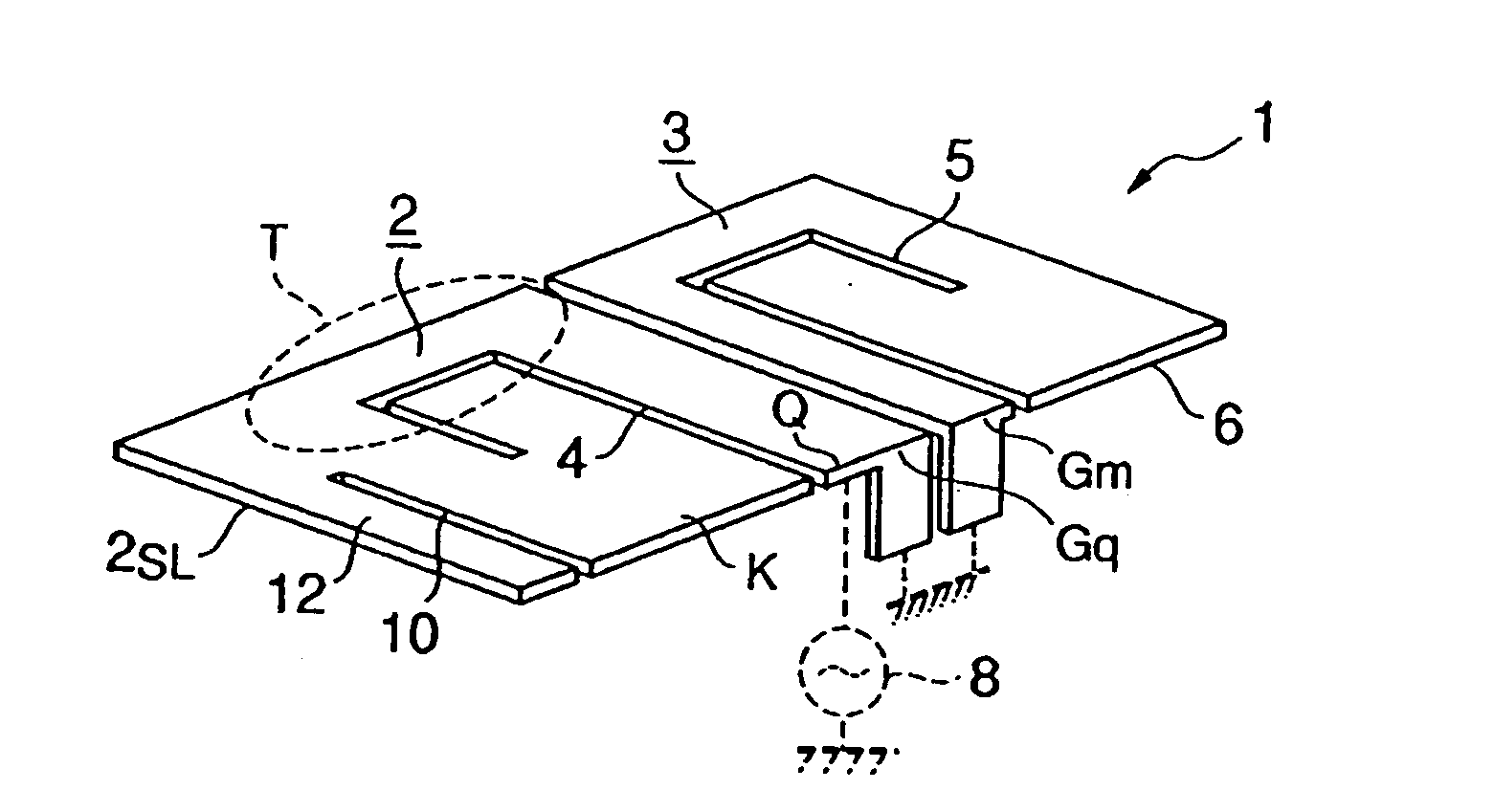
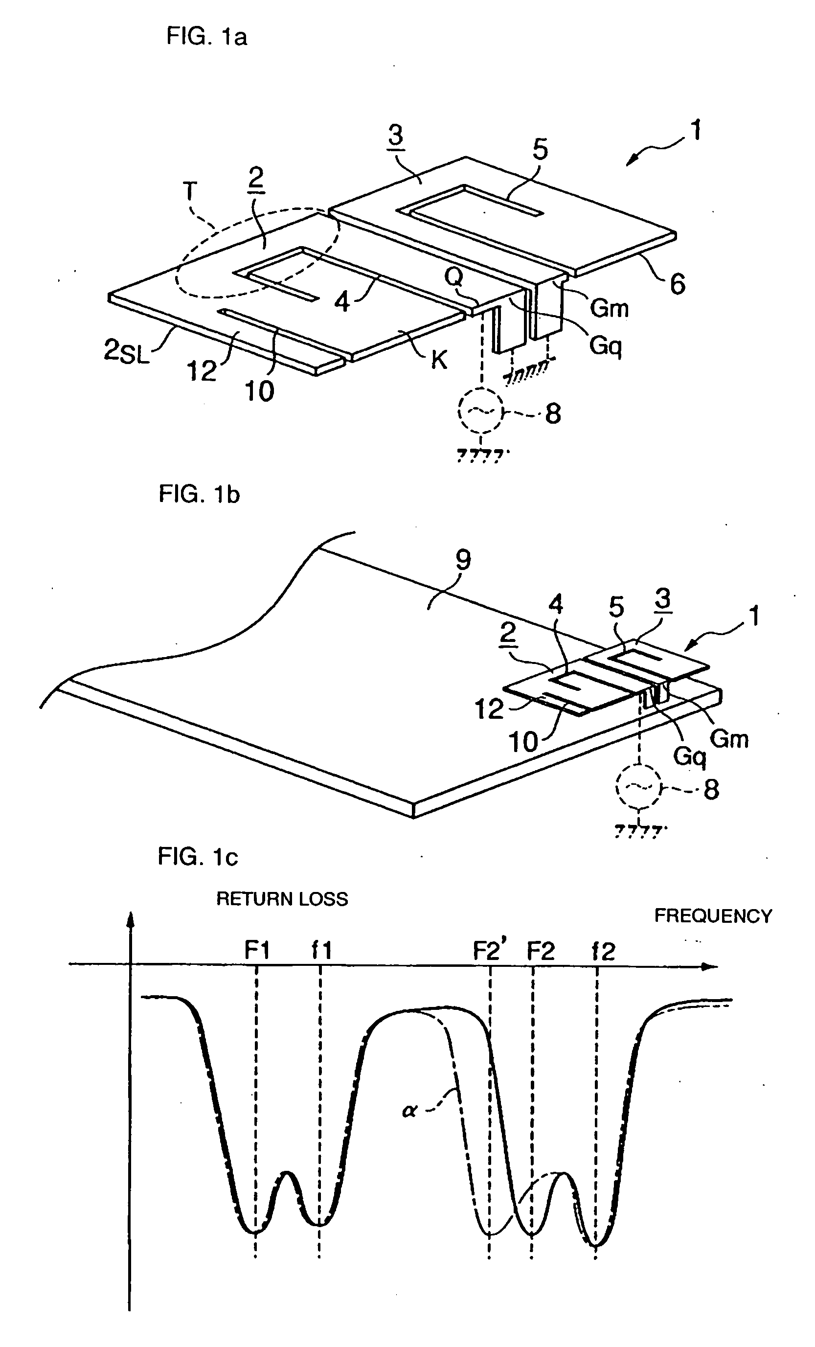
[0050] The antenna structure 1 includes the feeding radiation electrode 2 and the non-feeding radiation electrode 3. For example, as shown by the return loss characteristics represented by the solid line in FIG. 1c, the antenna structure 1 is capable of performing radio communication in four resonant frequency bands, that is, a fundamental resonant frequency band on a feeding side based on the fundamental resonant frequency F1 and a higher-order resonant frequency band on the feeding side based on the higher-order resonant frequency F2 of the feeding radiation electrode 2 and a fundamental resonant frequency band on a non-feeding side based on the fundamental resonant frequency f1 and a higher-order resonant frequency band on the non-feeding side based on the higher-order resonant frequency f2 of the non-feeding radiation electrode 3.

[0051] In addition, as shown in FIG. 1b, the feeding radiation electrode 2 and the non-feeding radiation electrode 3 are provided, for example, at an ...

second embodiment

[0063] In the second embodiment, as shown by a model diagram of FIG. 5, the feeding radiation electrode 2 has a shape in which the open stub 12 is bent toward the circuit substrate 9 in accordance with a virtual extension line β of the sub-slit 10 shown by a dotted line in FIG. 5.

[0064] In the second embodiment, since the open stub 12 is a portion that is not involved in radio wave radiation, the open stub 12 can be bent without considering deterioration of a radio wave radiation state. Due to bending of the open stub 12, the area of the circuit substrate 9 occupied by the antenna structure 1 (the feeding radiation electrode 2) can be reduced (that is, the antenna structure 1 can be miniaturized). The other structural features are similar to those in the first embodiment, and advantages similar to those of the first embodiment can be achieved.

[0065] A third embodiment is described next. In the explanation of the third embodiment, the same parts as in the first and second embodiment...

third embodiment

[0066] In the third embodiment, as shown in FIG. 6, the distance D between outline sides 2SR and 3SL, which face each other, of the feeding radiation electrode 2 and the non-feeding radiation electrode 3 that are adjacent to each other increases in a direction from the short-circuited portions Gq and Gm of the outline sides 2SR and 3SL toward an end E opposite to the short-circuited portions Gq and Gm.

[0067] The other structural features are similar to those in the first and second embodiments. In the example shown in FIG. 6, an example when the structure of the third embodiment is applied to the structure shown in the first embodiment is illustrated. However, the structure of the third embodiment may also be applied, for example, to the antenna structure 1 shown in the second embodiment in which the open stub 12 is bent.

[0068] Advantages similar to those in the first and second embodiments can be achieved in the third embodiment. In addition, the third embodiment achieves an advan...


PUM


Abstract

In an antenna structure including a feeding radiation electrode and a non-feeding radiation electrode that are electromagnetically coupled to each other, due to formation of a main slit, the feeding radiation electrode includes a U-turn portion in the middle of a path circumventing the main slit from a feeding end to an open end. A sub-slit for forming an open stub that is connected to the U-turn portion and that provides the U-turn portion with electrostatic capacitance is formed in the feeding radiation electrode. By changing a value of the electrostatic capacitance to be provided by the open stub to the U-turn portion of the feeding radiation electrode, variable control of a higher-order resonant frequency F2 of the feeding radiation electrode 2 can be achieved while suppressing fluctuations in a resonant state (for example, a fundamental resonant frequency F1 and a Q-value) of a fundamental resonant frequency band of the feeding radiation electrode, in an electromagnetic coupling state between the feeding radiation electrode and the non-feeding radiation electrode, and in an impedance matching state.

Description

CROSS REFERENCE TO RELATED APPLICATION [0001] The present application is a 35 U.S.C. §371 national phase conversion of PCT / JP2004 / 017788 filed Nov. 30, 2004, which claims priority of Japanese application no. JP2003-402544 filed Dec. 2, 2003, which are incorporated herein in their entirety. BACKGROUND OF THE INVENTION [0002] 1. Technical Field [0003] The present invention relates to an antenna structure capable of performing radio communication in a plurality of different frequency bands and to a communication apparatus including the antenna structure. [0004] 2. Background Art [0005]FIG. 11a schematically shows an example of an antenna structure capable of performing radio communication in a plurality of different frequency bands. An antenna structure 1 includes a feeding radiation electrode 2 and a non-feeding radiation electrode 3. The feeding radiation electrode 2 is a λ / 4 radiation electrode, and is formed by, for example, a conductor plate. A bent slit 4 including a U-shaped por...

Claims


Application Information

Patent Timeline
Patent Type & Authority Applications(United States)
IPC IPC(8): H01Q1/38H01Q1/24H01Q5/10H01Q5/342H01Q5/378H01Q5/385H01Q9/04H01Q13/08H01Q19/00H01Q21/30
CPCH01Q1/243H01Q9/0421H01Q9/0442H01Q5/392H01Q5/371H01Q5/378H01Q5/385H01Q19/005
Inventor KAWAHATA, KAZUNARIKURITA, JUNICHI
Owner MURATA MFG CO LTD
Why Eureka
Try Eureka