System and method for virtual chassis split prevention

a virtual chassis and split prevention technology, applied in the field of data networks, can solve the problems of difficult transition and difficulty in upgrading or transitioning from one type of network topology to another type of network topology

Active Publication Date: 2013-03-21
WSOU INVESTMENTS LLC
View PDF3 Cites 21 Cited by
  • Summary
  • Abstract
  • Description
  • Claims
  • Application Information

AI Technical Summary

Problems solved by technology

One of the key challenges faced by data networks is the need for network resiliency, i.e., the ability to maintain high availability despite eventual component failures, link failures or the like, which is critical to providing satisfactory network performance.
However, once implemented, it is sometimes ...

Method used


Image

  • System and method for virtual chassis split prevention
  • System and method for virtual chassis split prevention
  • System and method for virtual chassis split prevention

Examples


Embodiment Construction

[0032]The following standards are referred to in this application and are incorporated by reference herein: 1) the Link Aggregation Control Protocol (LACP) which was formerly clause 43 of the IEEE 802.3 standard added in March 2000 by the IEEE 802.3ad task force and is currently as incorporated in IEEE 802.1AX-2008 on Nov. 3, 2008; and 2) IEEE Std. 802.1Q, Virtual Bridged Local Area Networks, 2003 edition.

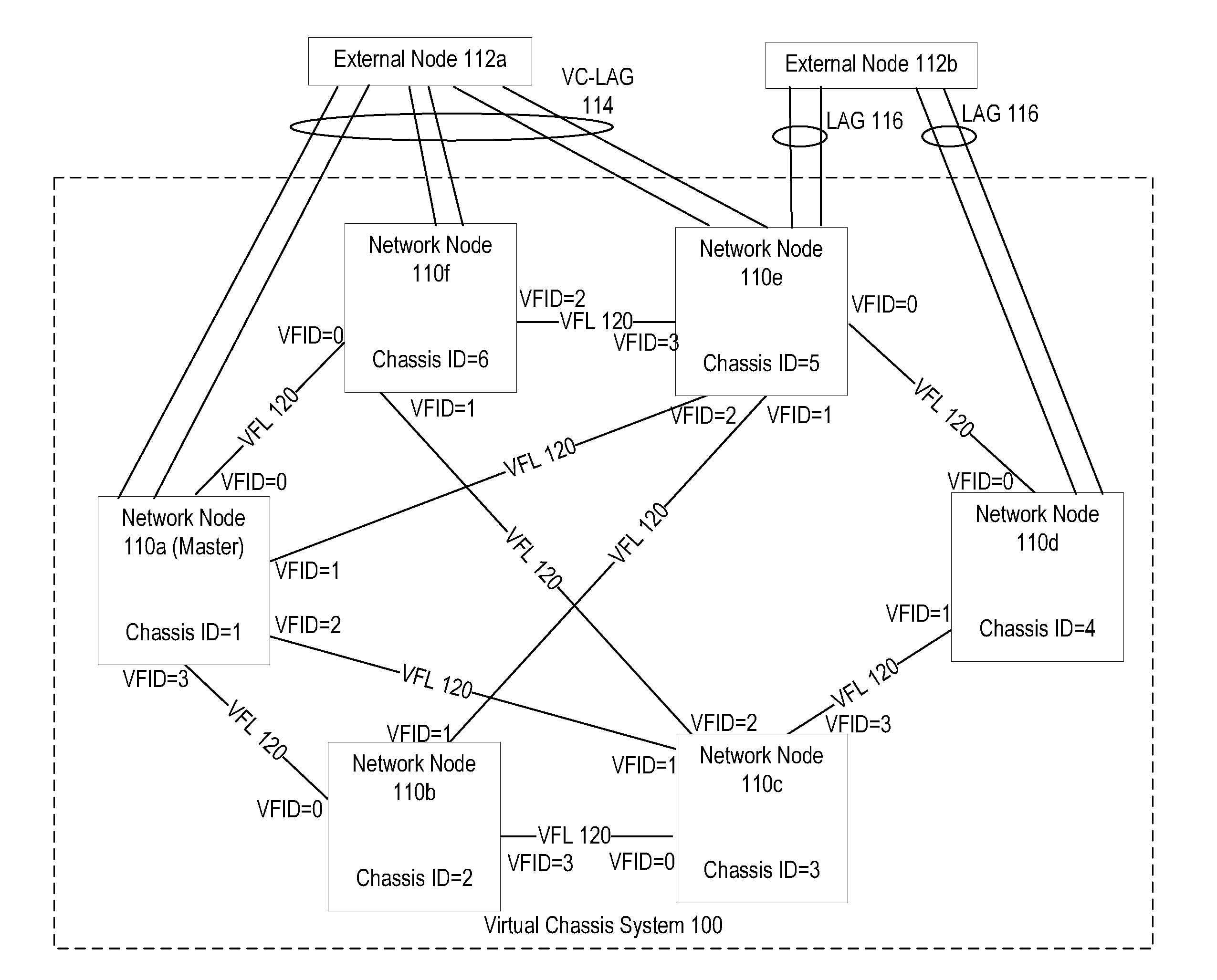
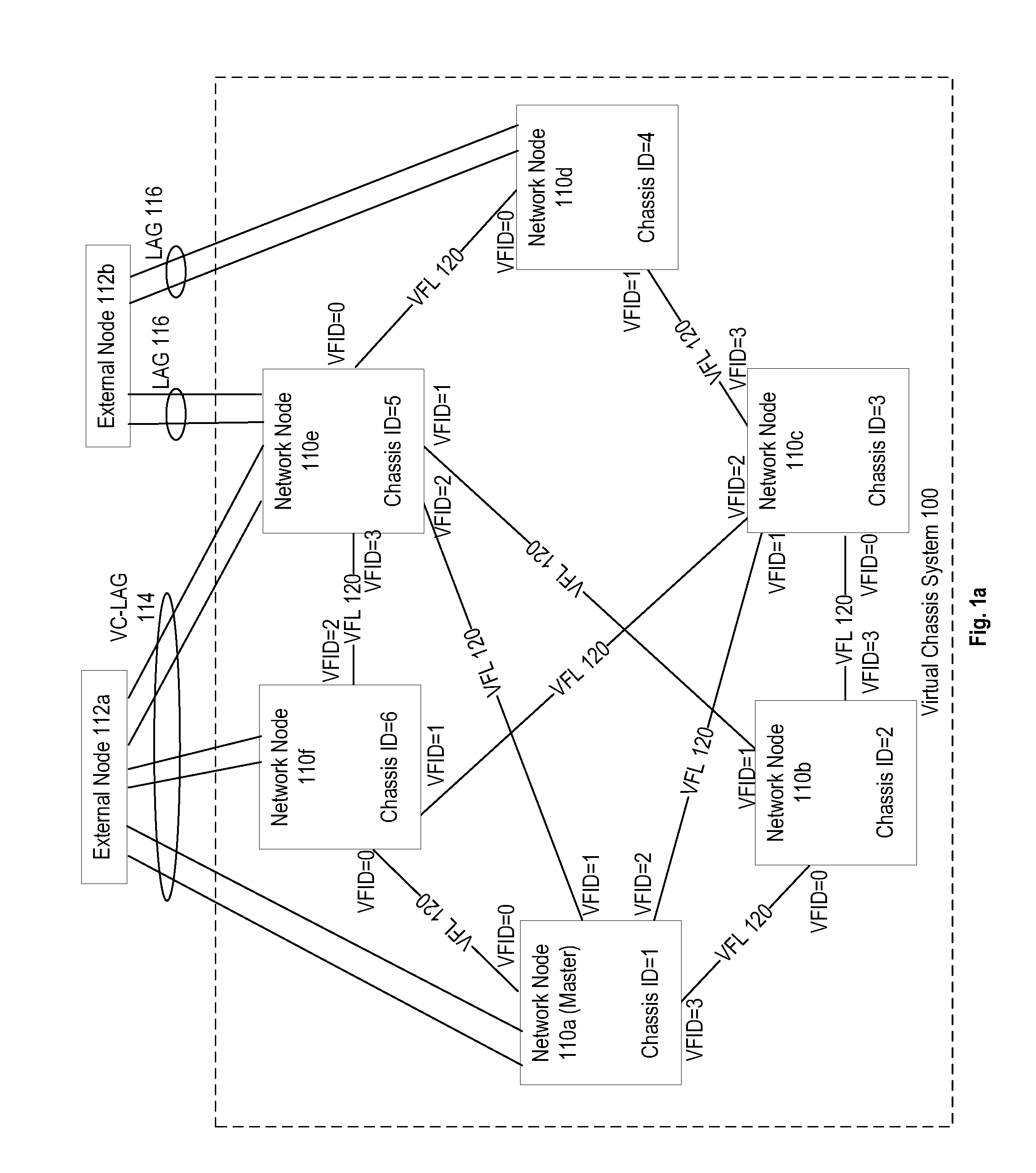
[0033]FIG. 1a illustrates an embodiment of a virtual chassis system 100 including a plurality of network nodes 110 operably coupled by dedicated link aggregate groups for communicating control and addressing information called virtual fabric links (VFLs) 120. VFLs 120 and their operation are described in more detail in U.S. patent application Ser. No. 13 / 010,168, entitled, “SYSTEM AND METHOD FOR MULTI-CHASSIS LINK AGGREGATION,” filed Jan. 20, 2011, pending, which is incorporated by reference herein and made part of the present U.S. Utility Patent Application for all purposes. The V...


PUM


Abstract

A virtual chassis system includes a plurality of network nodes configured with a master virtual chassis address. The network nodes are connected by virtual fabric link (VFLs) that provide a connection for exchange of packets between the network nodes. The virtual chassis system is operable to provide warnings to help prevent a virtual chassis split event in response to an administrative action. The topology of the virtual chassis system is analyzed to determine the possible impact of one or more administrative actions. Based on this analysis, a warning is generated when an administrative action is requested that may lead directly or indirectly to a virtual chassis split.

Description

CROSS-REFERENCE TO RELATED PATENTS[0001]The present U.S. Utility Patent Application claims priority as a continuation in part pursuant to 35 U.S.C. §120 to U.S. patent application Ser. No. 13 / 010,168, entitled, “SYSTEM AND METHOD FOR MULTI-CHASSIS LINK AGGREGATION,” filed Jan. 20, 2011, pending, which is incorporated by reference herein and made part of the present U.S. Utility Patent Application for all purposes and which claims priority pursuant to 35 U.S.C. §119(e) to U.S. Provisional Application Ser. No. 61 / 370,622, entitled, “MULTI-CHASSIS VIRTUAL-FABRIC LINK AGGREGATION SYSTEM,” filed Aug. 4, 2010, which is incorporated by reference herein and made part of the present U.S. Utility Patent Application for all purposes.[0002]The present U.S. Utility Patent Application claims priority pursuant to 35 U.S.C. §119(e) to U.S. Provisional Application Ser. No. 61 / 658,159, entitled, “VIRTUAL CHASSIS WITH GENERIC NODE ARCHITECTURE AND TOPOLOGY,” filed Jun. 11, 2012, which is incorporated ...

Claims


Application Information

Patent Timeline
IPC IPC(8): G06F15/173H04L45/24H04L45/243H04L45/28H04L45/58
CPCH04L45/58H04L45/22H04L45/245H04L49/40H04L49/552H04L49/70H04L45/28
Inventor HANKA, STEPHEN C.JACOB DA SILVA, ROBERTO H.WU, SHAOFUCHANG, AMY CHUNG-HUA
Owner WSOU INVESTMENTS LLC
Why Eureka
Try Eureka