Formliner Layout Member

a technology of layout member and formliner, which is applied in the field of formliner, can solve the problems of deformation of formliner, migration of specific joints, and noticeable changes in the resultant cured wall

Active Publication Date: 2013-03-28
ADVANCED FORMLINERS
View PDF15 Cites 9 Cited by
  • Summary
  • Abstract
  • Description
  • Claims
  • Application Information

AI Technical Summary

Benefits of technology

[0012]In some embodiments, a form liner system comprises a form liner sheet comprising a plurality of raised rows at a predetermined spacing, and a layout member comprising a base portion and a plurality of raised portions. The raised portions are constructed and arranged to nest with said raised rows.

Problems solved by technology

Formliners can suffer from problems of deformation due to applied loads and temperature change.
Temperature alone can change the actual dimensions of a formliner sheet and cause migration in the specific location of joints.
When casting a wall panel using multiple formliner sheets, slight changes in the size and / or shape of the individual formliner sheets can result in noticeable changes in a resulting cured wall, such as misalignment of brick coursings.
There has also been difficulty in creating a wall having an angle or joint, for example at locations where two non-parallel walls meet, along walls at recesses for doors and windows, etc.
Although this does create a formwork pattern, the formliners generally do not mate well or seal against one another, and concrete slurry can migrate between and behind the formliners.
This migration leads to imperfections in the finished panel.

Method used


Image

  • Formliner Layout Member
  • Formliner Layout Member
  • Formliner Layout Member

Examples


Embodiment Construction

[0031]While this invention may be embodied in many different forms, there are described in detail herein specific embodiments of the invention. This description is an exemplification of the principles of the invention and is not intended to limit the invention to the particular embodiments illustrated.

[0032]For the purposes of this disclosure, like reference numerals in the figures shall refer to like features unless otherwise indicated.

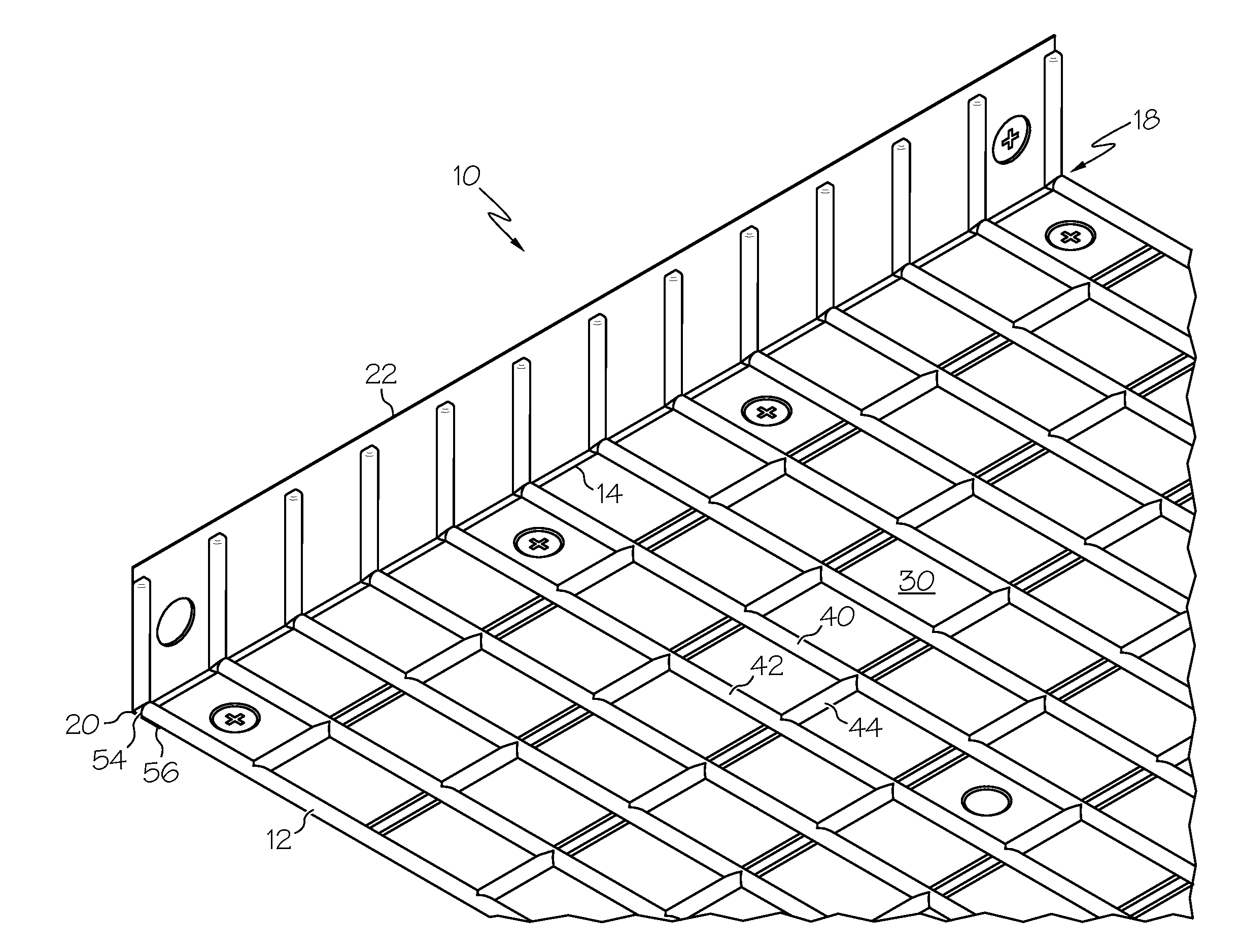
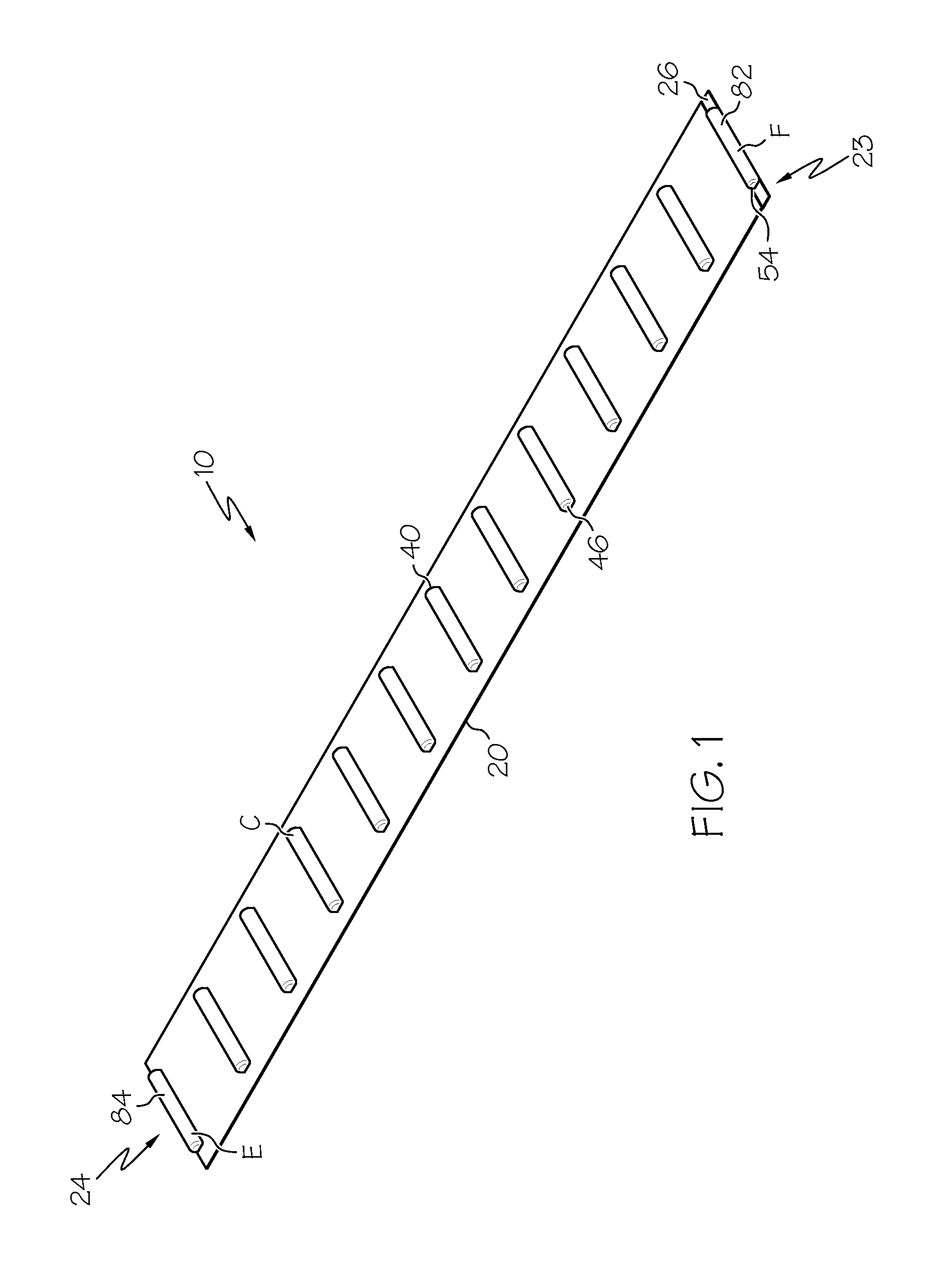
[0033]FIG. 1 shows an embodiment of a layout member 10. Desirably, a layout member 10 comprises a base portion 20 and a plurality of raised portions 40. Desirably, the raised portions 40 extend parallel to one another. In at least some embodiments, the raised portions 40 are spaced at regular intervals along a length of the base portion 20, such as being spaced according to a standard spacing of mortar joint rows in masonry construction.

[0034]In some embodiments, the base portion 20 extends outward beyond ends of the raised portions 40, wherein a wid...


PUM

PropertyMeasurementUnit
sizeaaaaaaaaaa
angleaaaaaaaaaa
lengthaaaaaaaaaa

Abstract

In some embodiments, a form liner system comprises a form liner sheet comprising a plurality of raised rows at a predetermined spacing, and a layout member comprising a base portion and a plurality of raised portions. The raised portions are constructed and arranged to nest with said raised rows.

Description

CROSS-REFERENCE TO RELATED APPLICATIONS[0001]This application claims the benefit of U.S. Patent Application No. 61 / 540,448, filed Sep. 28, 2011, the entire disclosure of which is hereby incorporated herein by reference.BACKGROUND OF THE INVENTION[0002]This invention relates generally to formliners and more specifically to a form liner layout member that helps to maintain proper spacing and orientation of formliner sheets, thereby providing a more desirable cured wall.[0003]Formliners are known in the industry and are often used with objects, such as “thin brick” inserts, to create a cast wall that appears to be traditional masonry. For example, thin bricks can be placed in a formliner that has a grid layout in a masonry pattern. Concrete can then be poured onto the formliner and thin bricks and allowed to cure, thus casting the thin bricks in the concrete panel. When the formliner is removed, the front face of the panel resembles traditional masonry. Some examples of formliners are ...

Claims


Application Information

Patent Timeline
Patent Type & Authority Applications(United States)
IPC IPC(8): B28B7/36B23P11/00
CPCB28B19/0061Y10T29/49826E04G9/10
Inventor CALMES, SHANE
Owner ADVANCED FORMLINERS
Why Eureka
Try Eureka