
Connector and connector assembly

a technology of connectors and connectors, applied in the direction of hose connections, packaging goods, packaged goods, etc., can solve the problems of not being able to feed safely and with certainty, and achieve the effect of preventing inadvertent separation of medical devices

Inactive Publication Date: 2013-03-28
TERUMO KK
View PDF14 Cites 90 Cited by
  • Summary
  • Abstract
  • Description
  • Claims
  • Application Information

AI Technical Summary

Benefits of technology

The present invention provides a connector and connector assembly that prevent the accidental separation of a medical device. The invention includes a separation preventing means that stops the main body portion from being separated from the outer tube after the weakly connecting portion is broken. This prevents any accidental disconnection of the device, which could be potentially dangerous.

Problems solved by technology

However, the conventional connector assembly has a drawback that, if the syringe or the lock adapter is rotated in a direction in which the screwing engagement is loosened, then it is separated simply.
Therefore, there is the possibility that the solution may not be fed with safely and certainty through the connector assembly.

Method used


Image

  • Connector and connector assembly
  • Connector and connector assembly
  • Connector and connector assembly

Examples


Embodiment Construction

[0044]In the following, a connector and a connector assembly of the present invention are described in detail based on a preferred embodiment shown in the accompanying drawings.

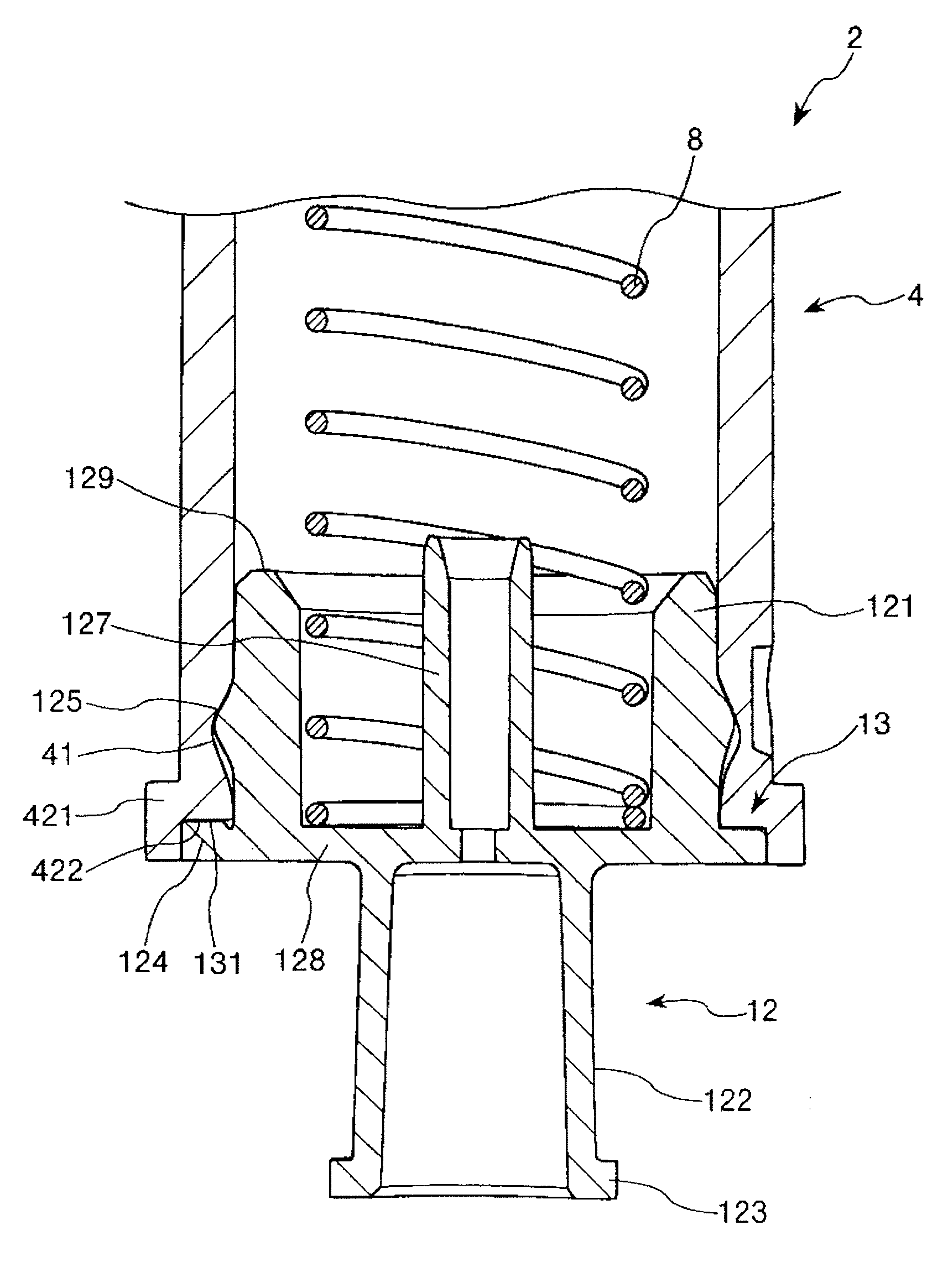
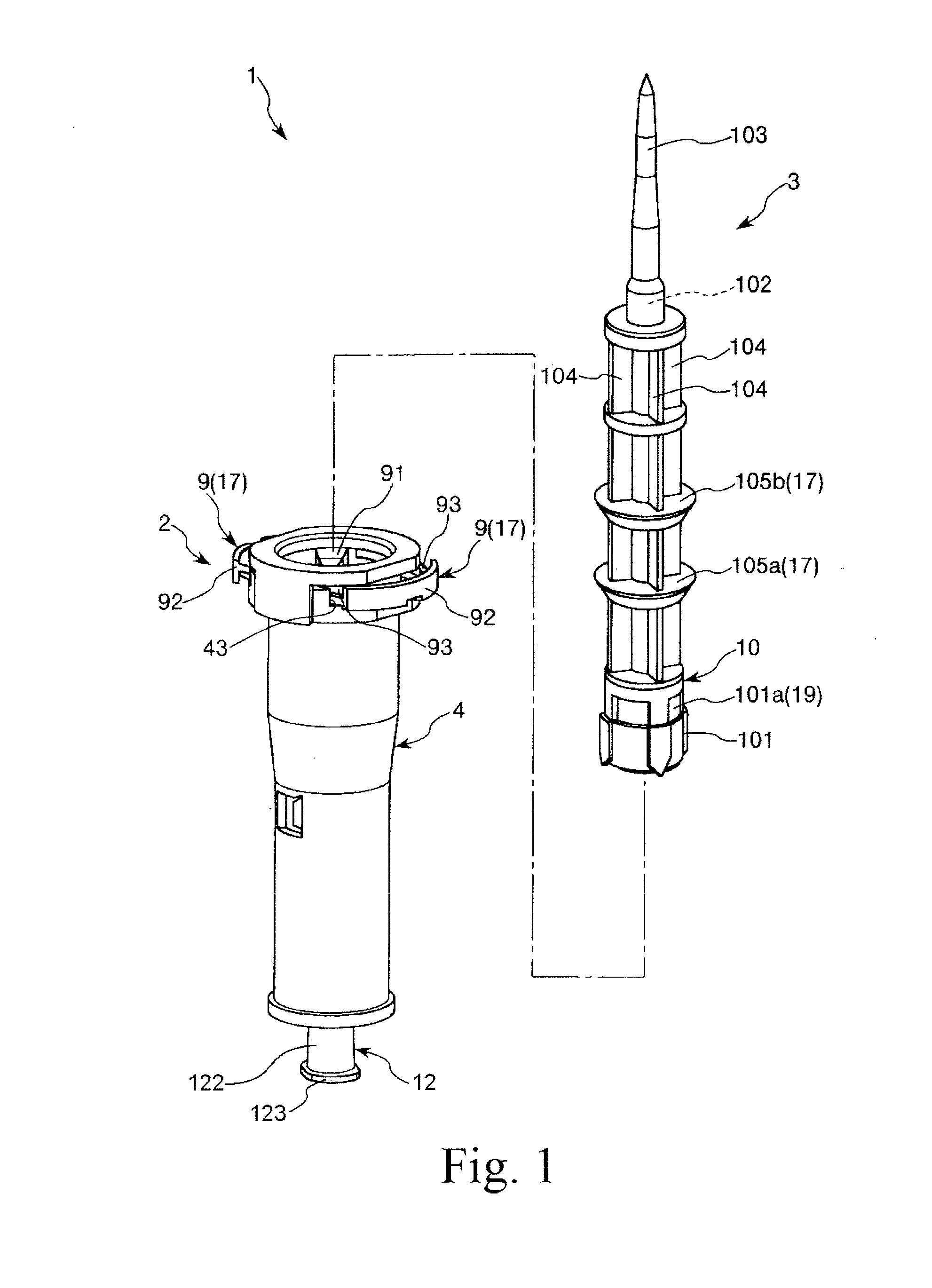
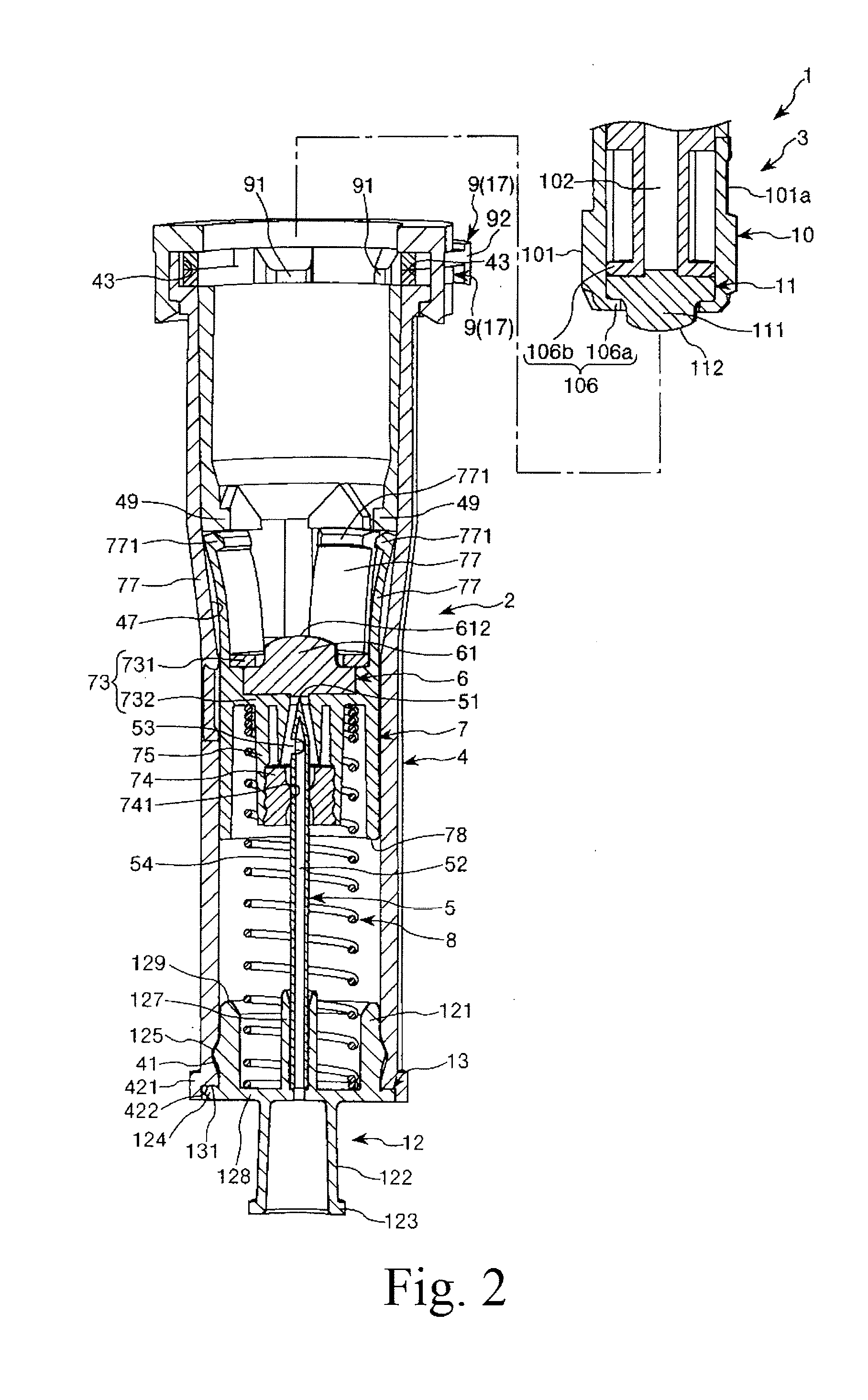
[0045]FIG. 1 is an exploded perspective view showing an embodiment of a connector assembly of the present invention; FIGS. 2 to 5 are vertical sectional views illustrating a process until a first connector and a second connector of the connector assembly shown in FIG. 1 are placed into an assembled state; FIGS. 6 to 9 are perspective views illustrating a process until the first connector and the second connector of the connector assembly shown in FIG. 1 are placed into the assembled state (views corresponding to FIGS. 2 to 5, respectively); FIG. 10 is a sectional view taken along line A-A of FIG. 3; FIG. 11 is a sectional view taken along line B-B of FIG. 4; FIG. 12 is a vertical sectional view (partial side elevational view) showing elements in the proximity of a proximal end portion of the first connector o...


PUM


Abstract

A first connector has a first connector main body configured from an outer tube having a cylindrical shape, an inner tube having a cylindrical shape and a hub, a hollow needle supported on the hub, a first sealing member supported on the inner tube, a coil spring serving as puncturing portion biasing means for biasing the first sealing member in a direction toward the distal end thereof, and a clamping member disposed on the outer tube. The hub is disposed at a proximal end portion of the outer tube. The hub is disposed such that, although the hub is initially connected to the outer tube by a breakable welded portion, when the welded portion is broken, the hub is permitted to rotate around an axis of the outer tube with respect to the outer tube.

Description

TECHNICAL FIELD[0001]The present invention relates to a connector and a connector assembly.BACKGROUND ART[0002]Usually, a drug such as an anti-cancer agent or an immunosuppressive agent which is dangerous if a health care worker touches by mistake is accommodated in a state of powder in a vial container which is sealed at a mouth portion thereof with a rubber stopper.[0003]In order to take out the drug from such a vial container as just described, the following operations are carried out.[0004]First, the mouth portion of the vial container and a mouth portion of a syringe into which liquid for dissolving has been dealt out are connected to each other through a connector assembly configured from a first connector and a second connector. In this instance, a lock adapter having screw threads formed on an inner circumferential face thereof is provided on an outer circumferential portion of the mouth portion of the syringe (refer to, for example, Patent Document 1), and when the syringe ...

Claims


Application Information

Patent Timeline
IPC IPC(8): A61M39/02
CPCA61J1/1475A61J1/2096A61J2001/201A61J2001/2065A61M5/1782A61M2039/1033A61M2039/1072A61M39/0208A61M39/1011A61J1/201A61J1/2065
Inventor TAKEMOTO, MASAFUMI
Owner TERUMO KK
Features
  • Generate Ideas
  • Intellectual Property
  • Life Sciences
  • Materials
  • Tech Scout
  • Unparalleled Data Quality
  • Higher Quality Content
  • 60% Fewer Hallucinations
Learn More