Surgical stereo vision systems and methods for microsurgery

a stereo vision and microsurgical technology, applied in the field of surgical stereo vision systems and methods, can solve the problems of limited number of oculars in the physical construction of the microscope, the inability to add additional content, and the main drawback of fov and z dependence still remains

Active Publication Date: 2013-03-28
DIGITAL SURGICALS
View PDF12 Cites 57 Cited by
  • Summary
  • Abstract
  • Description
  • Claims
  • Application Information

AI Technical Summary

Benefits of technology

[0014]In yet another exemplary embodiment, a method using a digital stereo microscope includes positioning and adjusting a display unit above an operating site; enabling the display unit, wherein the display unit comprises an optical system and an image acquisition system located on a side of the display unit adjacent to the operating site, and wherein the display unit comprises an image display on a side of the display unit opposite to the side facing the operating site; providing image capture and data capture of the area of interest via the optical system and the image acquisition system; processing the image capture and the data capture via a processing system; positioning a user's hands and / or tools in the operating site while maintaining the user's eyes having a view in a collocated manner looking at the image display; and presenting a magnified and augmented live stereo view of the operating site via the image display based on the processed image capture and the processed data capture of the area of interest from the optical system and the image acquisition system.

Problems solved by technology

Additional lighting innovations further increase the size, but the main drawback of FoV and Z dependence still remains.
In addition, physical construction of the microscope allows very limited numbers of oculars.
Optical microscopes do not allow additional content to be added to the view or enhance the view with mensuration or annotation.
Additionally, there are many usability issues in performing micro manipulations using SLMs.
A user of a SLM gets visual fatigue because the exit pupil diameter of the ocular lens is very small and lateral movements of the observer causes motion in the field of view.
This makes stereoscopic viewing through binocular microscope tedious and tiring.
This inconvenience adds to the operational time and operator fatigue.
Another limitation is the narrow field of view.
Narrow field causes the surgeons to lose the visual context frequently.
This too adds to the operational time and operator fatigue.
Many surgeries last hours and the fixed posture (looking through the eye pieces) contributes significantly to the fatigue experienced by surgeons.
Though magnified view is a significant surgical aid, due to the above limitations only very few surgeons are able to perform micro surgery, the surgery that uses microscopes, though there are far more surgeons with excellent surgical skills.
In the latter viewing setting, as the display 112 is located elsewhere, surgeon loses the key hand-eye collocation and as a result compromises the hand-eye coordination needed for highly dexterous manipulations under magnified view.
In addition, since the basic field of view is captured using the objectives of a traditional SLM, it suffers many of the limitations of the SLM described earlier.
However, SLMs or DSMs do not provide any visual aid to match the visual resolution variance.
Performing such variable resolution without depth distortion effects is also a challenge.
While the above system affords some freedom of head movement, the projected space is quite narrow and it is easy to slip out and loose stereo vision.
These microscopes have not found a home in operating theatres yet and are used in the manufacturing industry for inspection of printed circuit boards and other miniature electronic assemblies.

Method used


Image

  • Surgical stereo vision systems and methods for microsurgery
  • Surgical stereo vision systems and methods for microsurgery
  • Surgical stereo vision systems and methods for microsurgery

Examples


Embodiment Construction

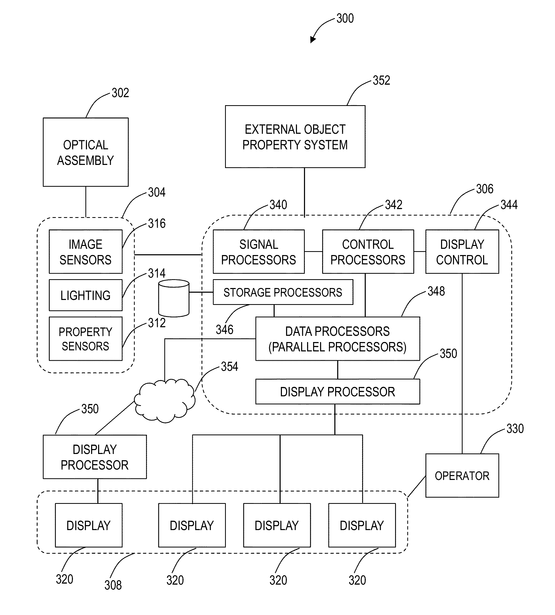
[0024]In various exemplary embodiments, surgical stereo vision systems and methods for microsurgery enable hand-eye collocation, high resolution, and a large field of view. Multiple multimodality sensors, including image sensors, capture properties of an object under the view of the system and the user's micro manipulations of the object. The captured live view is augmented with data from sensors and external databases to aid real-time micro manipulation of the object. The system provides multiple views on one or more flat-panel stereoscopic displays, collaborative manipulation of the object, real time measurements, and panning and tilting of the field of view without moving the object. The system supports microsurgical manipulations to be performed on a patient by a group of surgeons and imparts training to surgeons by recording and replaying the surgical manipulations with a phantom object in the field of view. The system includes a DSM that provides augmented and collocated live ...


PUM


Abstract

Surgical stereo vision systems and methods for microsurgery are described that enable hand-eye collocation, high resolution, and a large field of view. A digital stereo microscope apparatus, an operating system with a digital stereo microscope, and a method are described using a display unit located over an area of interest such that a human operator places hands, tools, or a combination thereof in the area of interest and views a magnified and augmented live stereo view of the area interest with eyes of the human operator substantially collocated with the hands of the human operator.

Description

CROSS-REFERENCE TO RELATED APPLICATION(S)[0001]The present non-provisional patent application claims priority to U.S. Provisional Patent Application Ser. No. 61 / 537,592 filed Sep. 21, 2011 and entitled “A Surgical Stereo Vision System for Microsurgery,” the contents of which are incorporated by reference herein.FIELD OF THE INVENTION[0002]Generally, the field of art of the present disclosure pertains to surgical vision systems and methods, and more particularly, to surgical stereo vision systems and methods for microsurgery that enable hand-eye collocation, high resolution, and a large field of view.BACKGROUND OF THE INVENTION[0003]Micromanipulations such as microsurgery require a distortion free magnified and binocular stereoscopic view of its operating field 101. Surgical Loupes, Surgical Light Microscope (SLM) and its digital adaptation, namely, Digital Stereo Microscope (DSM) provide such views of the operating field 101. SLMs have a number of optical elements that provide magni...

Claims


Application Information

Patent Timeline
Patent Type & Authority Applications(United States)
IPC IPC(8): H04N13/02
CPCH04N13/004G06T2210/41G06T11/00G02B21/22H04N13/156G16H40/63G16H20/40
Inventor RAPPEL, JAMES K.
Owner DIGITAL SURGICALS
Why Eureka
Try Eureka