

Optical pickup and optical read/write apparatus
a technology of optical pickup and optical read/write, which is applied in the direction of digital signal error detection/correction, instruments, recording signal processing, etc., can solve the problem of difficulty in increasing the write ra
- Summary
- Abstract
- Description
- Claims
- Application Information
AI Technical Summary
Benefits of technology
Problems solved by technology
Method used
Image

Examples
embodiment 1
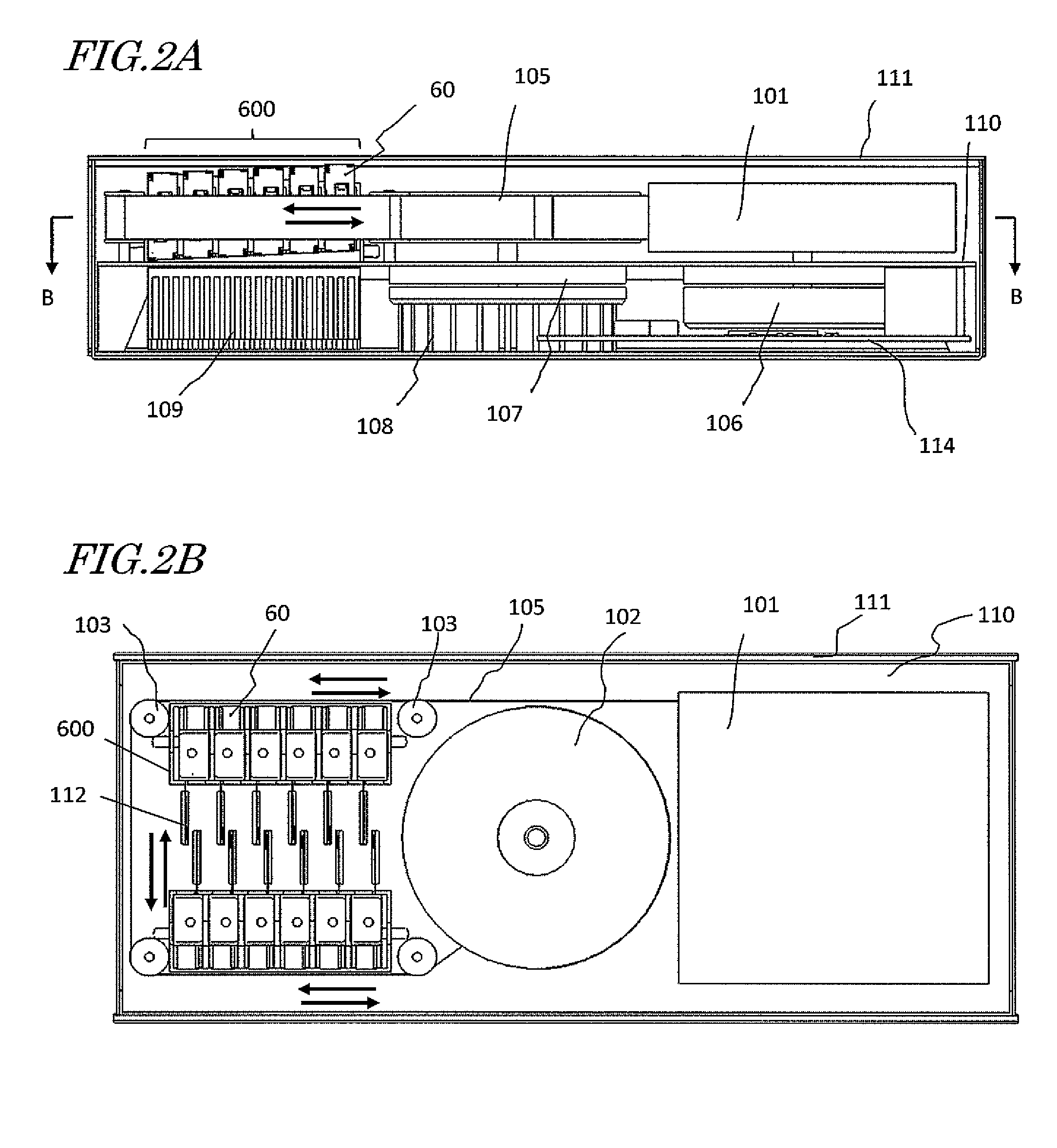
[0076]Hereinafter, embodiments of an optical read / write apparatus according to the present disclosure will be described. An optical read / write apparatus as an embodiment of the present disclosure is an optical data streamer apparatus that uses an optical tape as an optical storage medium. Such an optical data streamer apparatus may be used to back up a huge quantity of data. In order to back up such an enormous quantity of data in a short time with the transfer rate increased, the optical data streamer apparatus includes a lot of optical pickups. It should be noted that the optical read / write apparatus of the present disclosure does not have to be an optical data streamer apparatus but may also be an optical disc apparatus or any other kind of apparatus. In the case of an optical disc apparatus, the optical storage medium is not an optical tape but an optical disc.
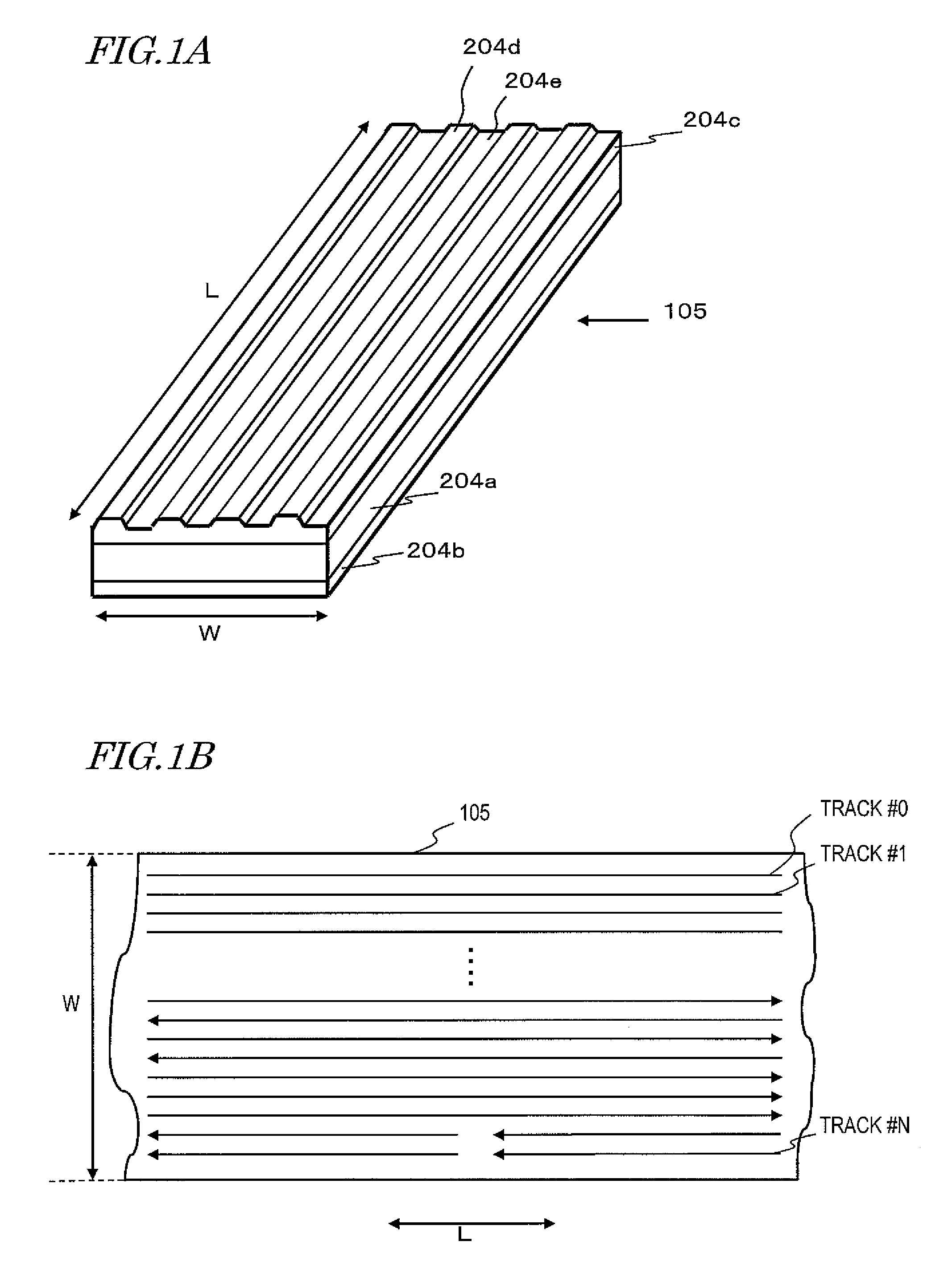
[0077]FIG. 1A is a perspective view schematically illustrating a portion of an optical tape 105 on a larger scale. The o...
embodiment 2
[0128]Next, an optical pickup as a second embodiment of the present disclosure will be described.
[0129]The basic arrangement of this embodiment is the same as what is illustrated in FIG. 4. Thus, in the following description of this second embodiment, FIG. 4 will be referred to again as needed.
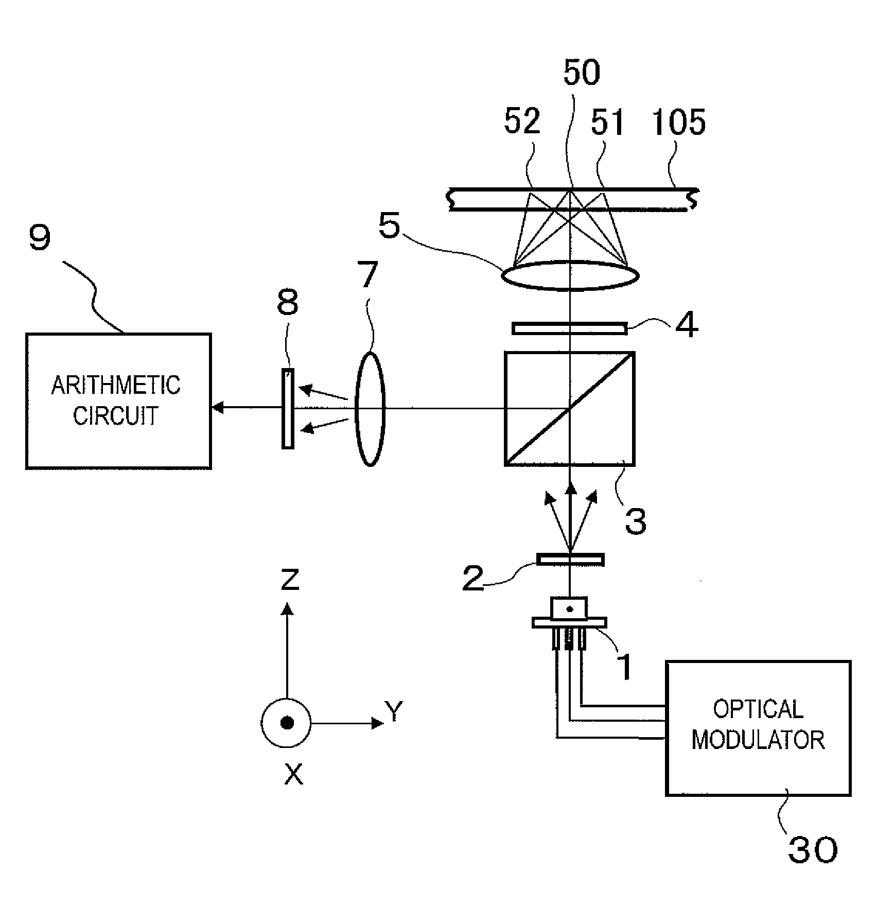
[0130]FIG. 13A illustrates a configuration for the photodiodes of the photodetector 8 of this embodiment and also is a block diagram of a circuit that carries out signal processing using its section from the photodetector 8 through the arithmetic circuit 9. FIG. 13B is an enlarged view of the sub-photodiode 11. Of the two sub-spots 51 and 52 of the ±first-order light beams shown in FIG. 5, what is received by the sub-photodiode 11 is the reflected light that has left the sub-spot 51 illustrated as the upper one on the paper. That is to say, the sub-beam received by the sub-photodiode 11 is the light that has left the sub-spot 51 on the mark 70 that has just been recorded with the main spot 50....
embodiment 3
[0137]Hereinafter, an optical pickup as a third embodiment of the present disclosure will be described.
[0138]FIG. 16 illustrates the arrangement of an optical system for the optical pickup of this embodiment.
[0139]In this embodiment, an optical extractor 21 is arranged between the polarization beam splitter 3 and the photodetector 8. In the example to be described below, a diffractive element that acts on only a part of the beam as shown in FIG. 17 is supposed to be used as the optical extractor 21. In the optical extractor 21 of this example, the central portion of the beam effective diameter is a diffraction grating 22, of which the grating vector points a 45 degree direction obliquely.
[0140]The light that has been reflected from the optical tape 105 and then incident on the optical extractor 21 gets diffracted by this diffraction grating 22, transmitted through the detector lens 7, and then is incident on a photodetector.
[0141]FIG. 18 illustrates a configuration for the photodiod...
PUM
 Abstract
Description
Claims
Application Information