Pore-Limit Electrophoresis (PLE) Microchannel Assays

Inactive Publication Date: 2013-03-28
RGT UNIV OF CALIFORNIA
View PDF2 Cites 7 Cited by
  • Summary
  • Abstract
  • Description
  • Claims
  • Application Information

AI Technical Summary

Problems solved by technology

Microfluidic devices designed to carry out complex analyses may have complicated networks of intersecting channels with some of the channels being open to the outside of the microfluidic devices through one or more wells.

Method used


Image

  • Pore-Limit Electrophoresis (PLE) Microchannel Assays
  • Pore-Limit Electrophoresis (PLE) Microchannel Assays
  • Pore-Limit Electrophoresis (PLE) Microchannel Assays

Examples


Embodiment Construction

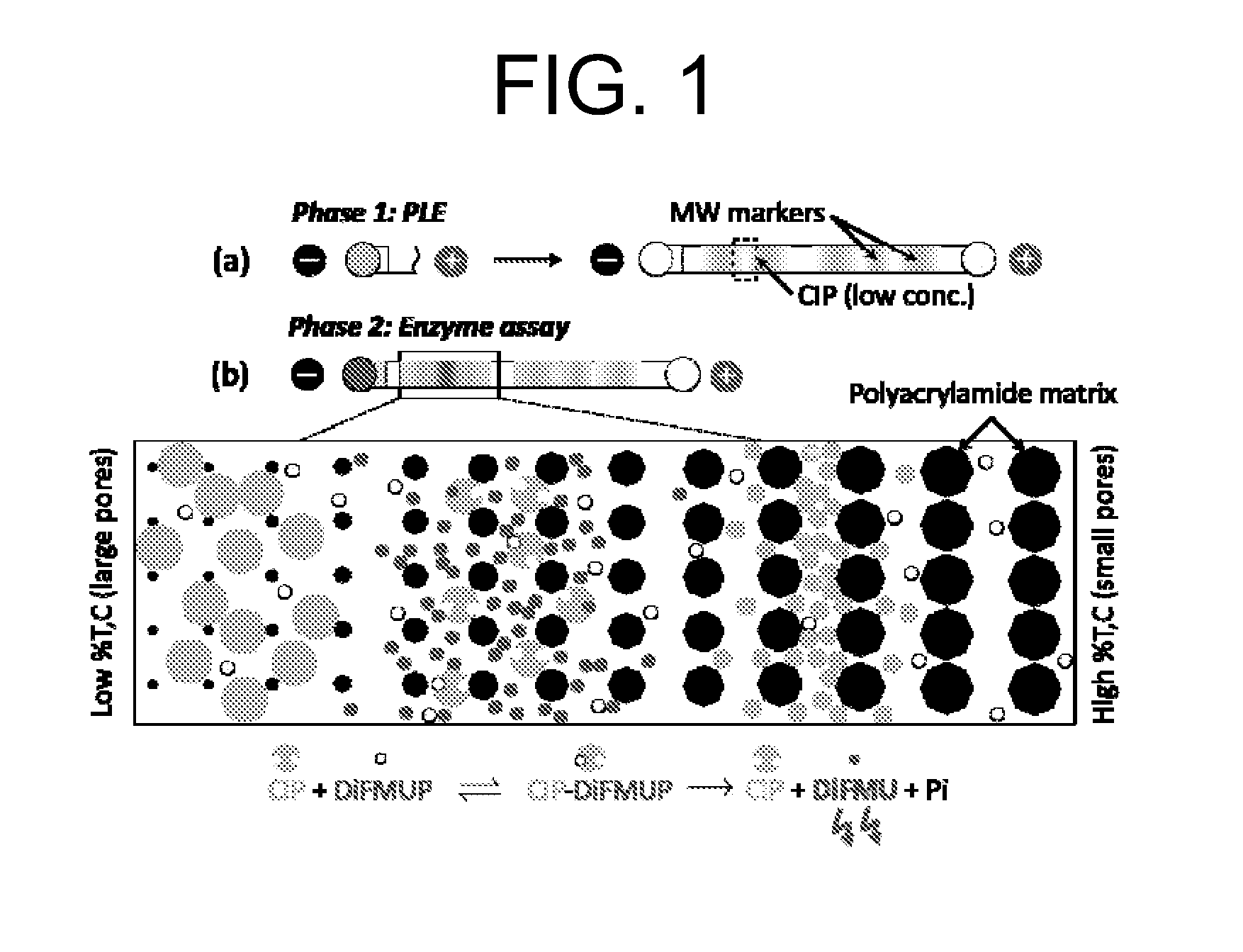
[0030]Pore-limit electrophoresis (PLE) microchannel assay methods are provided. Aspects of the methods include sequentially introducing samples at least suspected of containing first and second assay members into a PLE microchannel and then evaluating the microchannel for interaction between the first and second assay members. Aspects of the invention further include devices, systems and kits configured for practicing methods of invention. The methods, devices, systems and kits of the invention find use in a variety of different applications, including enzyme activity assays and immunoassays.

[0031]Before the present invention is described in greater detail, it is to be understood that this invention is not limited to particular embodiments described, as such may, of course, vary. It is also to be understood that the terminology used herein is for the purpose of describing particular embodiments only, and is not intended to be limiting, since the scope of the present invention will b...


PUM

PropertyMeasurementUnit
radiusaaaaaaaaaa
constant currentaaaaaaaaaa
lengthaaaaaaaaaa

Abstract

Pore-limit electrophoresis (PLE) microchannel assay methods are provided. Aspects of the methods include sequentially introducing samples at least suspected of containing first and second assay members into a PLE microchannel and then evaluating the microchannel for interaction between the first and second assay members. Aspects of the invention further include devices, systems and kits configured for practicing methods of invention. The methods, devices, systems and kits of the invention find use in a variety of different applications, including enzyme activity assays and immunoassays.

Description

CROSS-REFERENCE TO RELATED APPLICATIONS [0001]Pursuant to 35 U.S.C. §119(e), this application claims priority to the filing date of U.S. Provisional Patent Application Ser. No. 61 / 266,060, filed Dec. 2, 2009, which application is incorporated herein by reference in its entirety.REFERENCE TO GOVERNMENT SUPPORT [0002]This invention was made in part with government support under grant no. N66001-09-1-2118 awarded by DARPA. The government has certain rights in this invention.INTRODUCTION [0003]Microfluidics refers to a set of technologies involving the flow of fluids through channels having at least one linear interior dimension, such as depth or radius, of less than 1 mm. It is possible to create microscopic equivalents of bench-top laboratory equipment such as beakers, pipettes, incubators, electrophoresis chambers, and analytical instruments within the channels of a microfluidic device. Since it is also possible to combine the functions of several pieces of equipment on a single micr...

Claims


Application Information

Patent Timeline
Patent Type & Authority Applications(United States)
IPC IPC(8): C12Q1/28
CPCG01N27/44791C12Q1/28G01N33/561
Inventor HERR, AMY E.CHEN, XIOFANG
Owner RGT UNIV OF CALIFORNIA
Why Eureka
Try Eureka