Belt Tensioning Device For A Belt Drive And Apparatus With A Belt Tensioning Device

a technology of tensioning device and belt drive, which is applied in the direction of belt/chain/gearing, mechanical apparatus, gearing, etc., can solve the problems of particularly compact design, and achieve the effect of compact design, compact design and small radial installation spa

Active Publication Date: 2013-03-28
MUHR UND BENNDER KG
View PDF2 Cites 52 Cited by
  • Summary
  • Abstract
  • Description
  • Claims
  • Application Information

AI Technical Summary

Benefits of technology

[0010]Because the belt tensioning device can be mounted directly on the apparatus, a compact design is achieved in an advantageous way. More particularly, the belt tensioning device can be arranged at the end face of the apparatus so that there is no need for providing a separate installation space between the crankshaft and the apparatus. In addition, there is no need for any further connecting means for the belt tensioning device at the engine block. Overall, the belt tensioning device can be designed independently of the packaging and the space requirements of the engine. Because the pivot axis of the tensioning arm is arranged inside the outer diameter of the belt pulley, the belt tensioning device, in an axial view, is positioned inside an envelope of the apparatus so that the radial installation space is small.
[0011]According to a preferred embodiment, the base is designed such that, in the mounted condition of the belt tensioning device on the apparatus, the pivot axis of the tensioning arm is arranged inside the outer diameter of the driveshaft, more particularly coaxially relative to the axis of rotation of the driveshaft. This results in a particularly compact design.
[0014]According to a second possibility, the belt tensioning device is designed such that the bearing for the tensioning arm at the base is positioned in the region between the housing and the belt pulley of the apparatus. This means that a central plane of the bearing is arranged between the apparatus and the central plane of the belt. This also applies to the torsion spring, which tensions the tensioning arm relative to the base and which is also positioned between the central plane of the belt and the apparatus. This embodiment is particularly suitable for a belt tensioning device which is produced so as to be integral with the apparatus, i.e., which has a single-piece design with the apparatus. According to a preferred embodiment, the base of the belt tensioning device and the housing of the apparatus can be produced in one piece. In this way, the number of components is kept small, the production and mounting procedures are simplified, and there is achieved a particularly compact construction.
[0017]According to a preferred embodiment, the base comprises an aperture into which the driveshaft of the apparatus at least partially extends into in a mounted condition. This means that at least a partial portion of the driveshaft axially overlaps with the base wall surrounding the aperture. This embodiment contributes to an axially short construction. In an advantageous further embodiment, the aperture is provided in the form of a through-aperture, by means of which the mounting procedure of the belt pulley on the driveshaft and, respectively, the mounting procedure of the belt tensioning device on the apparatus, are simplified. The through-aperture of the base has an internal diameter that is preferably greater than the outer diameter of the driveshaft, more particularly greater than the outer diameter of the belt pulley. This embodiment ensures that the belt tensioning device and, respectively, the tensioning arm can be easily and comfortably attached to the apparatus. The belt tensioning device and, respectively, the tensioning arm are placed on to the apparatus, with the driveshaft of the apparatus entering the through-aperture of the base and of the tensioning arm, respectively. This design is particularly suitable for the second possibility, wherein the bearing for the belt tensioning device is arranged between the apparatus and the belt, comprising a particularly compact construction because the base and the housing form one part. However, the construction with the through-aperture in the tensioning arm is also suitable for the first possibility. If the inner diameter of the through-aperture is greater than the outer diameter of the belt pulley, the belt tensioning device can easily be mounted in a condition in which the belt pulley has already been mounted.

Problems solved by technology

This results in a particularly compact design.

Method used


Image

  • Belt Tensioning Device For A Belt Drive And Apparatus With A Belt Tensioning Device
  • Belt Tensioning Device For A Belt Drive And Apparatus With A Belt Tensioning Device
  • Belt Tensioning Device For A Belt Drive And Apparatus With A Belt Tensioning Device

Examples


first embodiment

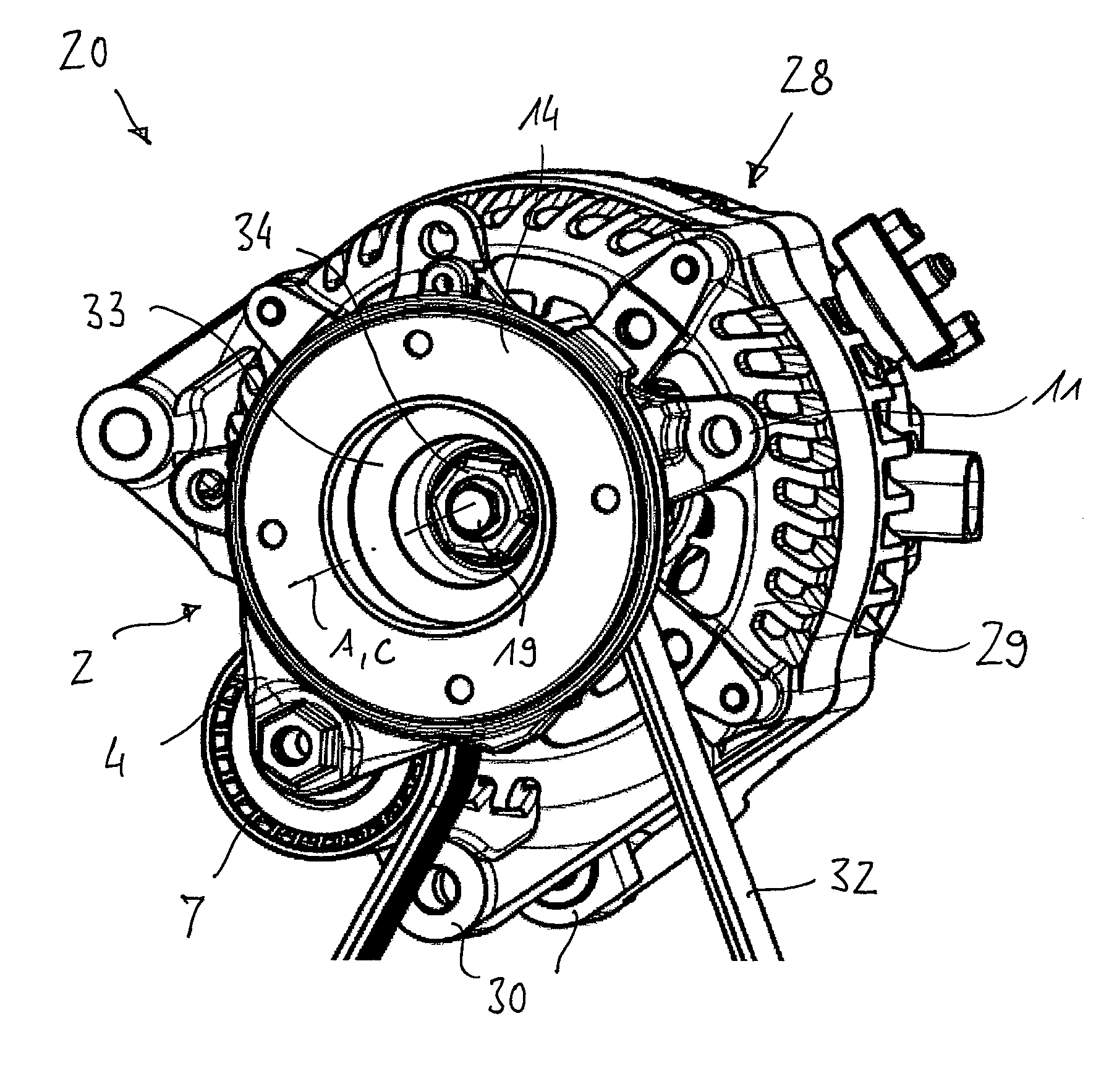
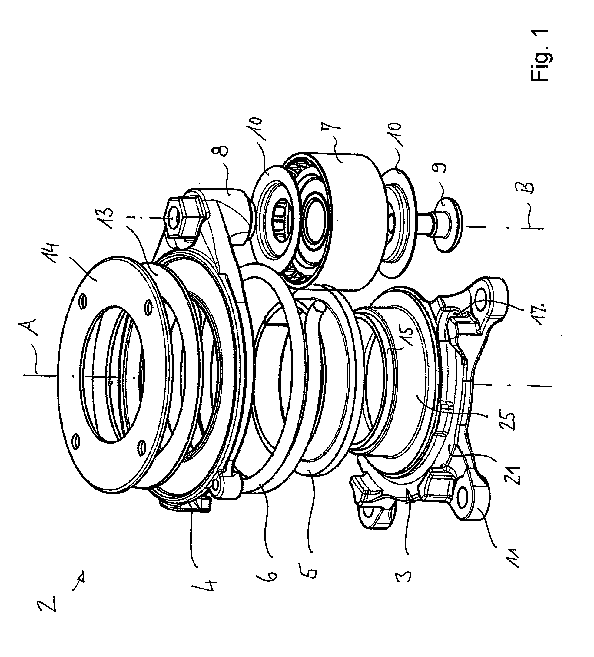
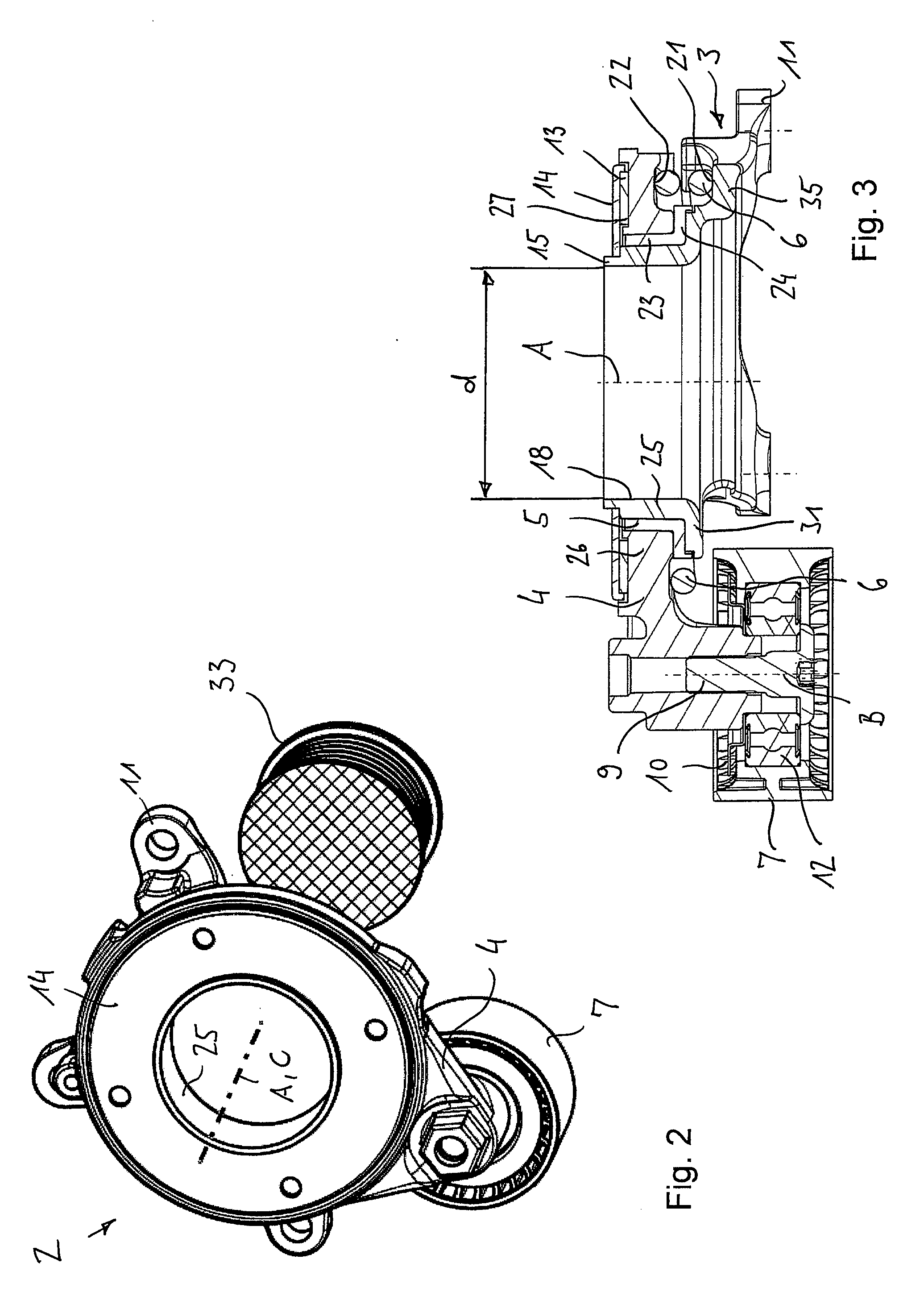
[0027]FIGS. 1 to 3, which will be described jointly below, show an inventive belt tensioning device 2 in a The belt tensioning device 2 comprises a base 3, which can be fixed to an auxiliary apparatus of an engine or to a part connected to the apparatus and a tensioning arm 4 that, by means of a bearing 5, is supported relative to the base 3 so as to be pivotable around a pivot axis A and that, via a torsion spring 6, is circumferentially supported relative to the base 3. The engine can be of any kind, such as an internal combustion engine or an electric motor for driving a vehicle. For fixing the base 3, it comprises three radially outwardly projecting flange portions 11 with boreholes through which bolts can be inserted for being fixed to the apparatus 28.

[0028]At a free end portion, the tensioning arm 4 carries a tensioning roller 7, which is rotatable around an axis of rotation B extending parallel to the pivot axis A. The tensioning roller 7 is rotatably supported at a bearing...

second embodiment

[0038]FIGS. 5 and 6 show an inventive belt tensioning device 2 and an inventive apparatus arrangement 20 in a These embodiments largely correspond to those of FIGS. 1 to 4 so that, as far as the common features are concerned, reference is made to the above description. Identical or modified parts have been given the same reference numbers as in FIGS. 1 to 4. Below, there will follow a description mainly of the differences between the embodiments.

[0039]One special feature of the present embodiment consists in that the bearing 5 of the belt tensioning device 2 is arranged axially between the apparatus 28 and the belt pulley 33. The bearing journal 8 for the tensioning roller 7 points away from the apparatus 28. It can also be seen that the base 3 of the belt tensioning device 2 is produced so as to be integral, more particularly so as to form one piece with the housing 29 of the apparatus 28. In an advantageous way, this leads to a reduction in the number of components required. Furt...


PUM


Abstract

A belt tensioning device for a belt drive having at least one apparatus with a housing, a driveshaft and a belt pulley, as well as an infinite belt for driving the belt pulley. The belt tensioning device includes a base that can be or is firmly connected to the apparatus, exactly one tensioning arm that, relative to the base, is supported so as to be pivotable around a pivot axis and that, via a torsion spring, is supported in the circumferential direction against the base. The belt tensioning device also includes a tensioning roller that, at the tensioning arm, is supported so as to be rotatable around an axis of rotation and serves to tension the belt. When the belt tensioning device is mounted at the apparatus, the pivot axis of the tensioning arm is arranged inside the outer diameter of the belt pulley of the apparatus.

Description

BACKGROUND OF THE INVENTION[0001]The invention relates to a belt tensioning device for a belt drive which comprises an infinite belt and at least two belt pulleys of which one can function as an input and one as an output. Such belt drives are used more particularly in connection with internal combustion engines of motor vehicles for driving auxiliary apparatuses or accessories, wherein a first belt pulley is positioned on the crankshaft of the internal combustion engine and drives the belt. Further, belt pulleys are associated with the auxiliary apparatuses, such as a water pump, a generator, or an air conditioning compressor and are rotatingly driven by the belt. In conventional belt drives, the auxiliary apparatuses are designed as consumers, i.e., they are driven by the belt pulley of the crankshaft via the belt. A slack side of the belt is formed between the crankshaft and the apparatus adjoining the crankshaft in the direction of circulation of the belt, the adjoining apparatu...

Claims


Application Information

Patent Timeline
Patent Type & Authority Applications(United States)
IPC IPC(8): F16H7/12
CPCF16H7/1281F16H2007/0893F16H2007/081
Inventor SCHAUERTE, STEFANJUD, JOACHIMPFEIFER, SIMONJUNG, MANFRED
Owner MUHR UND BENNDER KG
Why Eureka
Try Eureka