Spinal rod and bone screw caps for spinal systems assemblies

a technology of spinal system and spine, applied in the field of spinal rod and bone screw caps for spinal system assemblies, can solve the problems of 4.5 million patients who fail conservative therapy, are left with debilitating pain, and inconvenience for surgeons, and achieve the effect of reducing the surgeon's/her time during the operation, preventing slippage and disassembly, and reducing the time of operation

Inactive Publication Date: 2013-03-28
SIMONSON PETER M
View PDF10 Cites 27 Cited by
  • Summary
  • Abstract
  • Description
  • Claims
  • Application Information

AI Technical Summary

Benefits of technology

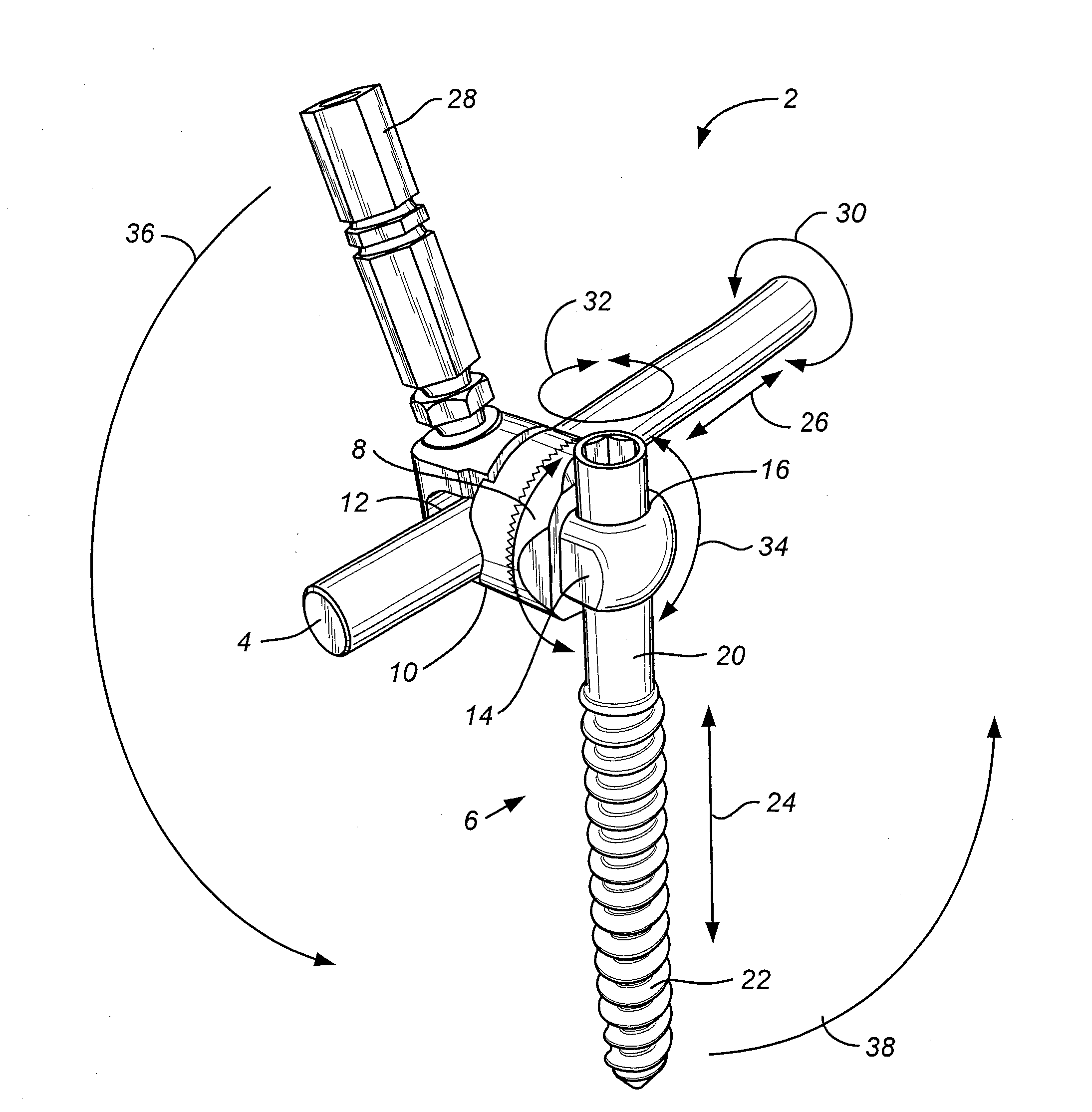
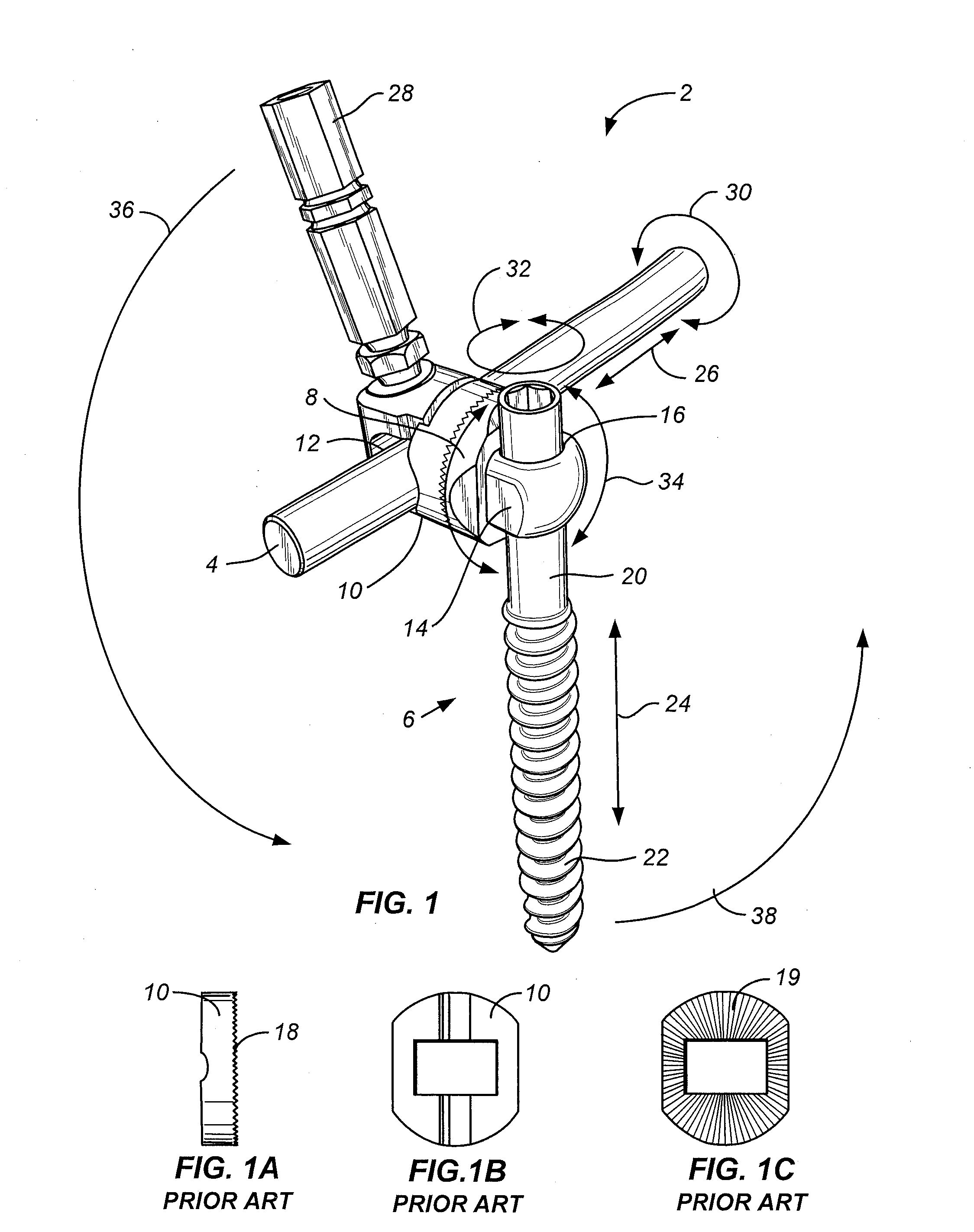
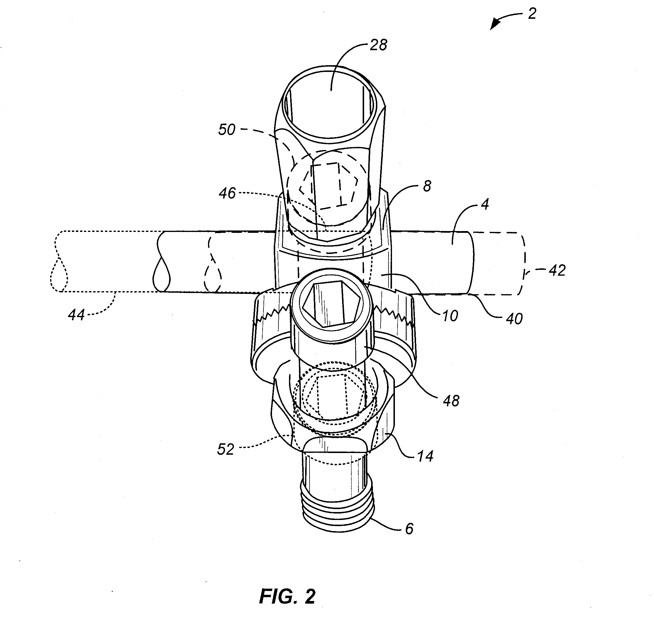
[0015]In one embodiment, the present invention is a cap or c-clip on either a bone screw or rod or both to prevent slippage and disassembly of spinal system assemblies along or off their respective rods or bone screws during intra-operative construction or post-operative stress. The cap or c-clip makes it more convenient for the surgeon to put together the spinal system assembly and thereby reduces his / her time during the operation. With such caps, spinal system assemblies will not come apart before spinal compression and final tightening of the set screw.
[0016]To attach a cap to the rod or bone screw, threads on the ends of spinal rods and / or bone screws may be used. With corresponding threads, a cap can be easily placed onto a rod or bone screw. Furthermore, a threaded cap can be removed to either disassemble or modify parts of spinal system assemblies.
[0017]Another preferred embodiment is similar to the first but is more easily placed and removed. This embodiment is a c-clip that snaps into a groove positioned at or near the end of spinal rods or bone screws. Such a groove is cut into and around the end of a bone screw or rod. In some circumstances, a c-clip may be preferable to the threaded cap because the rods and bone screws do not need to be threaded. There are two types of c-clip embodiments. One is a c-clip that is intended to be an alternative to the threaded cap. It contains a lip with a hole so that it can be easily pushed onto the spinal rod or bone screw thereby making it more easily and quickly placed. The other embodiment is a lighter c-clip similar to a spring and made of alloy metals. It may be used intra-operatively and removed when the set screw is tighten.
[0018]Like the earlier cap embodiment, the c-clip embodiments also allows the pre-operative construction of the spinal system assembly. When pre-assembled, the c-clip makes it more convenient for the surgeon and will reduce his / her time putting the assemblies together during the operation. With such c-clips, spinal system assemblies will not come apart before final spinal compression and tightening. Like the earlier cap embodiment, a c-clip can also prevent slippage and disassembly of the spinal system assemblies along or off their respective rods or bone screws either during intra-operative construction or post-operative stress.
[0019]In the long run, the present cap and c-clip embodiments may also serve as backup or fail-safe devices. Over time, loads or forces on the spinal implants weaken bone screws and their connectors along spinal rods. In rare instances, a bone screw may pull out from the vertebral body and start to pull the spinal system assembly apart. If the cap and c-clip embodiments are present, they may prevent or mitigate a total disassembly of the spinal system assembly by acting as end plates or stoppers to ensure the connectors or washers on either the bone screw or rod do not become detached from each other. Even if loosened, the connector assembly can still retain some of its support with either the cap or c-clip holding the connector assembly in place until such time when implants can be retighten, replaced or fusion is complete.

Problems solved by technology

Nonetheless, approximately 15 percent, or 4.5 million, fail conservative therapy and are left with debilitating pain.
Although not critical, such a scenario is inconvenient for the surgeon because he / she may have to re-assemble the connector assemblies.
Although not critical, such a scenario is inconvenient for the surgeon because he / she may have to re-assembly the connector assemblies.
Over time, these micro-motions may lead to a progressive degradation of the spinal system assemblies 2 from their initially implanted state.
During such degradation, there may be pressure or forces weakening the spinal system compression points.
Over time, these pressures or forces may lead to movement or slippage along the rods 4 or, in worst-case scenario, metal fatigue and eventual breakage.

Method used


Image

  • Spinal rod and bone screw caps for spinal systems assemblies
  • Spinal rod and bone screw caps for spinal systems assemblies
  • Spinal rod and bone screw caps for spinal systems assemblies

Examples


Embodiment Construction

[0036]Referring to FIG. 3A, a threaded cap 56 is shown which screws on to spinal rod threads 54 on the end of spinal rod 4. As shown in FIG. 3B, the cap 56 has a threaded aperture 58 into which spinal rod threads 54 from a spinal rod 4 are screwed. Typically, the spinal rod 4 has male threads, while the cap 56 has female threads. However, the gender of the spinal rod 4 and cap 56 may be reversed where the spinal rod 4 comprises female threads and the cap 56 has male threads. One preferred embodiment is a smooth and round cap 60. Such a smooth and round cap 60 can be easily placed onto the spinal rod 4, screwed into a spinal rod threads 54 and finger-tightened by a surgeon. If a more secure cap is desired, a wrench cap 62 with flat sides 64 such as shown in FIG. 3C may be used. A wrench cap 62 is similar to a washer or nut with flat sides. In this embodiment, the two flat sides 64 allow a small hand wrench to torque the wrench cap 62 a little tighter than finger tightening. Although ...


PUM

PropertyMeasurementUnit
anglesaaaaaaaaaa
rigidityaaaaaaaaaa
lengthaaaaaaaaaa

Abstract

A threaded cap or c-clip that attaches to a spinal rod or bone screw. Such a threaded cap or c-clip prevents slippage of the spinal system assemblies along or off their rods or bone screws during intra- or post-operative periods.

Description

FIELD OF INVENTION[0001]The present invention relates to devices, implants and tools used in orthopedic spinal surgical procedures. Specifically, the invention improves spinal system assemblies with a threaded cap or c-clip for securing spinal rods and bone screws.BACKGROUND OF THE INVENTION[0002]Back pain is a commonly reported medical aliment. It is most frequently associated with degenerative changes in the spinal vertebra. Most of the 30 million people in the U.S. reporting back pain each year resolve their pain with conservative treatment, or simply rest and exercise. Nonetheless, approximately 15 percent, or 4.5 million, fail conservative therapy and are left with debilitating pain. Out of these, approximately 500,000 people opt for spinal surgery. In addition to alleviating pain, spinal surgery seeks to minimize damage to adjacent supportive muscle and skeletal components.[0003]Several techniques and systems have been developed for correcting and stabilizing the spine and, wh...

Claims


Application Information

Patent Timeline
Patent Type & Authority Applications(United States)
IPC IPC(8): A61B17/70B23P11/00
CPCA61B17/7004A61B17/7041Y10T29/49826A61B17/88A61B17/8872A61B17/8685
Inventor SIMONSON, PETER M.
Owner SIMONSON PETER M
Why Eureka
Try Eureka