Supercharge Your Innovation With Domain-Expert AI Agents!

Brake assembly

a technology of brakes and components, applied in the field of elevator systems, can solve the problems of liner sticking to the moveable, machine may not be able to operate, and the situation of brake sticking can be difficult and/or time-consuming to remedy

Inactive Publication Date: 2013-04-04
OTIS ELEVATOR CO
View PDF5 Cites 2 Cited by
  • Summary
  • Abstract
  • Description
  • Claims
  • Application Information

AI Technical Summary

Benefits of technology

The patent text describes an elevator brake component that is used in a friction brake for elevators. This component has a metal plate that is engaged with another brake component when the elevator brake is engaged. The metal plate has a non-stick finish on its surface, which prevents any sticking or friction when the brake is pressed together. The technical effect of this non-stick finish is that it improves the performance and durability of the elevator brake.

Problems solved by technology

Under certain conditions, prolonged contact between the liner and the plates may cause the liner to stick to the moveable plate and / or the fixed plate.
Without disengagement of the liner and plate(s), the machine may not be able to operate since the liner / plate sticking prevents the shaft from rotating.
With machineroomless elevator systems (in which the machine resides in the hoistway rather than in a conventional machine room), this brake sticking scenario can prove difficult and / or time consuming to remedy.

Method used


Image

  • Brake assembly
  • Brake assembly
  • Brake assembly

Examples


Embodiment Construction

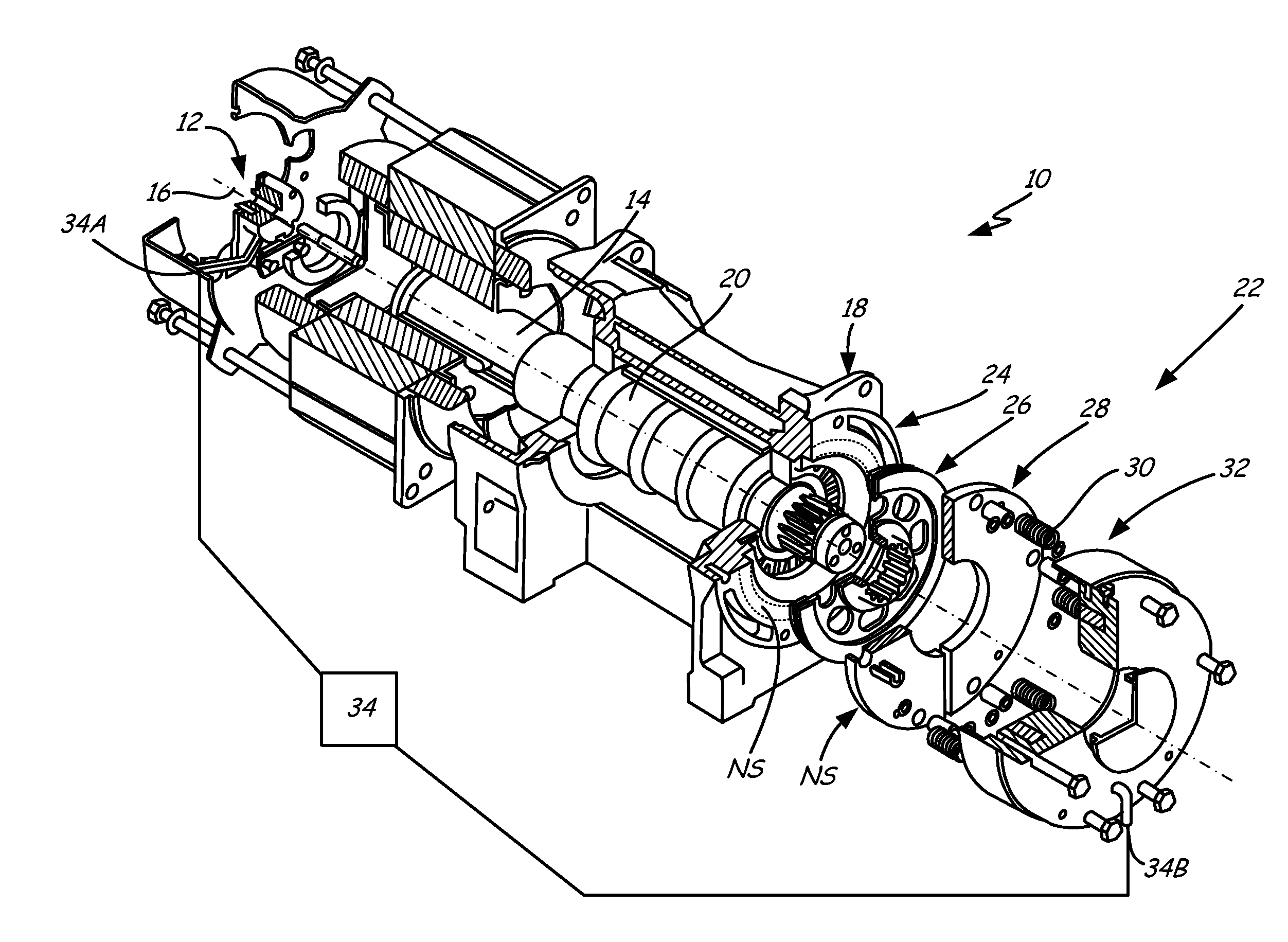
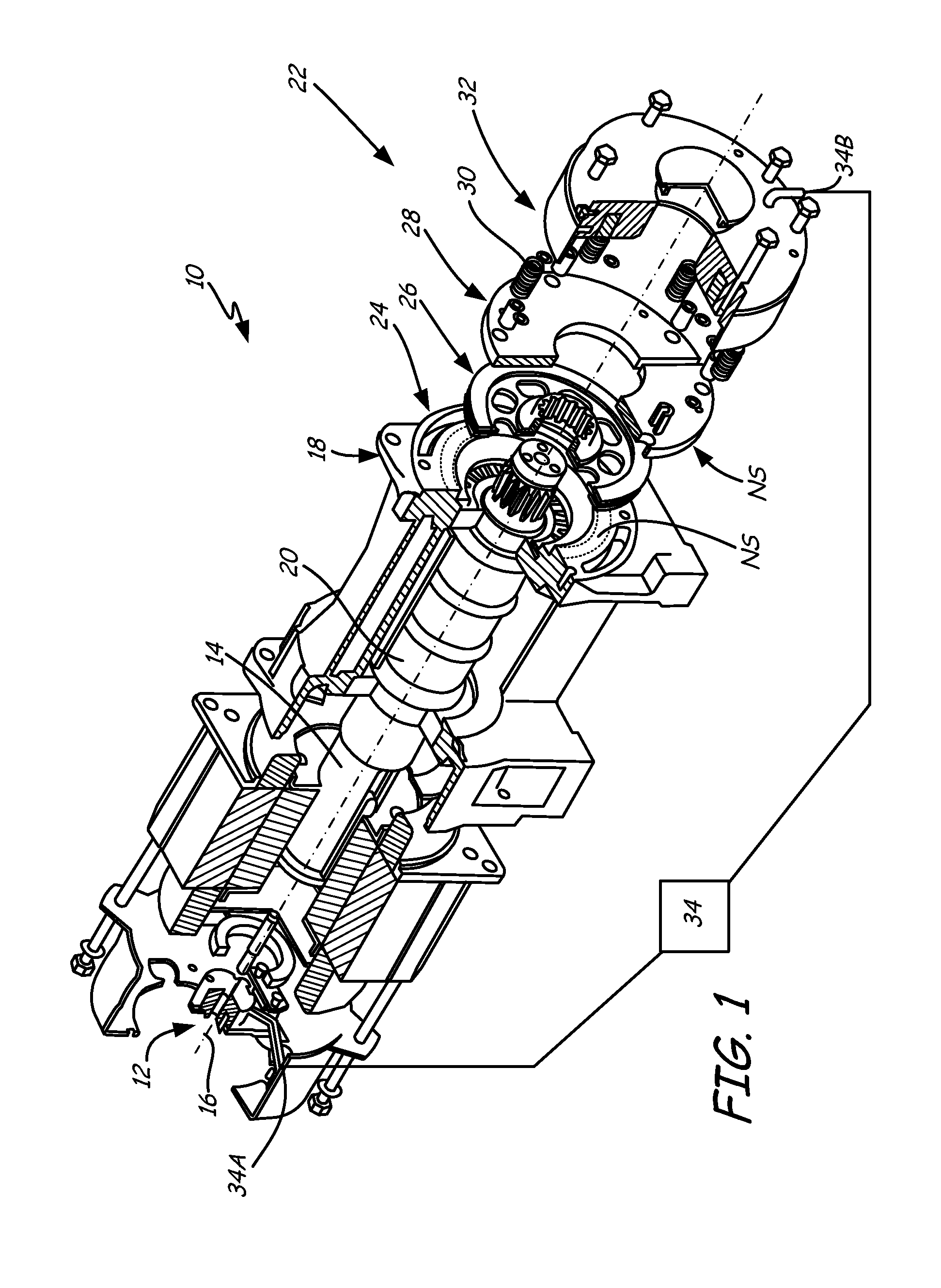
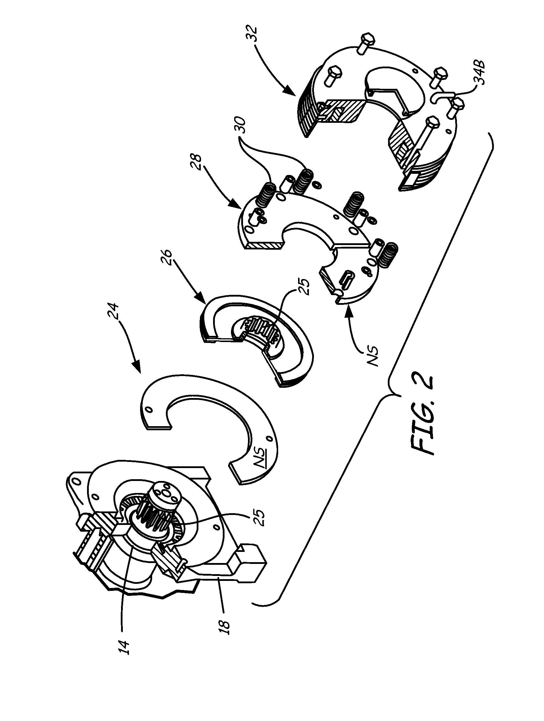
[0011]FIG. 1 is an exploded view of one possible embodiment of an elevator drive machine including a clutch brake assembly. Elevator drive machine 10 could be, for example, a gearless permanent magnet machine that includes an electric motor 12, shaft 14 which rotates around axis 16, housing 18, sheave 20 brake assembly 22 for applying a braking force to the machine 10 such as through the shaft 14 and electrical wiring 34A, 34B connecting the machine to controller 34, located at any suitable location. As will be explained in further detail below, the brake assembly 22 includes fixed plate 24, liner 26, movable plate 28, springs 30, and housing 32 that includes electromagnet 33.

[0012]Motor 12 is connected to shaft 14 to rotationally drive shaft 14. Shaft 14 also connects to sheave 20 (alternatively, sheave 20 could be an integral part of shaft 14) and liner 26. Fixed plate 24 is part of housing 18 in this embodiment. Movable plate 28 (which could be an annular disk or formed from mult...


PUM

PropertyMeasurementUnit
roughnessaaaaaaaaaa
frictional forcesaaaaaaaaaa
movementaaaaaaaaaa

Abstract

An elevator brake component used in a friction brake of an elevator includes a metal plate that is frictionally engaged with another brake component when the elevator brake is engaged. The plate includes a non-stick finish on the metal plate on a surface of the plate that is frictionally engaged when the elevator brake is engaged by the other brake component.

Description

BACKGROUND OF THE INVENTION [0001]Typical elevator systems can include an elevator car attached to a counterweight by roping. A drive machine, which includes a motor and a brake, rotates and acts (typically by traction) on the roping (that could be round ropes or flat belts) that engages the machine to move the elevator car and counterweight up and down an elevator hoistway, transporting passengers or cargo from one floor to another. An elevator controller controls operation of the elevator system. The drive machine is typically located at the top of the hoistway.[0002]When an elevator call is registered, the controller sends a signal to the drive machine to raise or lower the car to the call floor, and then apply the brake on the machine as the elevator approaches the call floor. One possible brake for the drive machine is a clutch brake, which consists of a fixed plate, a movable plate, springs and an electromagnet for moving the movable plate, and a liner located between the fixe...

Claims


Application Information

Patent Timeline
Patent Type & Authority Applications(United States)
IPC IPC(8): B66B1/36F16D65/092F16D55/02F16D65/18
CPCB66D5/14B66D5/30F16D55/2245F16D65/12F16D65/092F16D2250/0046H02K7/1021B66B1/36F16D55/02F16D2121/22
Inventor ILLAN, JUAN ANTONIOSANDOVAL, JOSE MARIAMARTIN-MARTIN, JUANSANCHEZ-PALENZUELA, ANTONIO
Owner OTIS ELEVATOR CO
Features
  • R&D
  • Intellectual Property
  • Life Sciences
  • Materials
  • Tech Scout
  • Unparalleled Data Quality
  • Higher Quality Content
  • 60% Fewer Hallucinations
Learn More