Linear motor
a linear motor and motor shaft technology, applied in the direction of dynamo-electric machines, electrical apparatus, magnetic circuit shapes/forms/construction, etc., can solve problems such as cogging, and achieve the effect of reducing cogging and reducing variation in magnetic attraction forces
- Summary
- Abstract
- Description
- Claims
- Application Information
AI Technical Summary
Benefits of technology
Problems solved by technology
Method used
Image
Examples
example 1
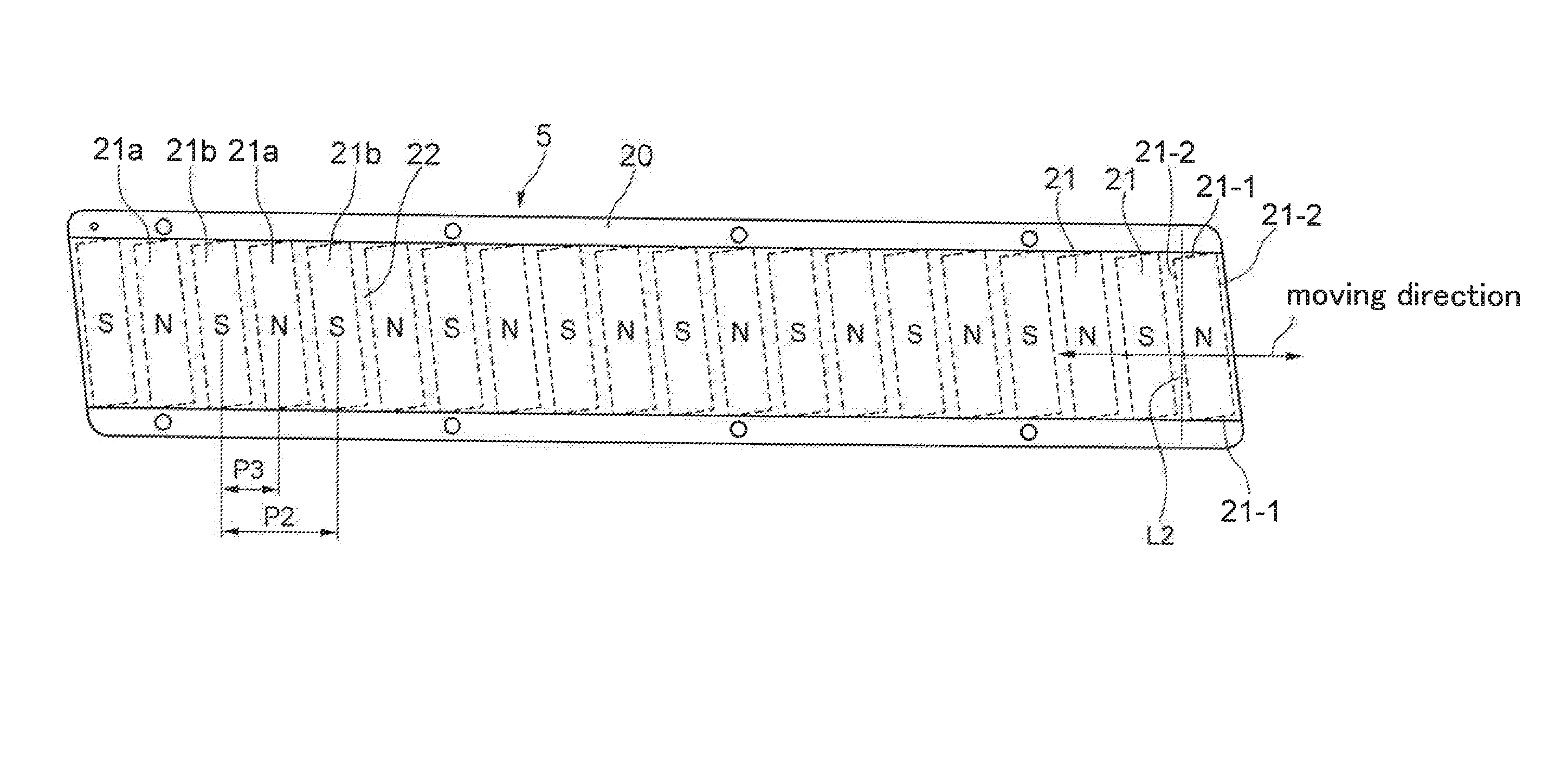
[0056]By the magnetic field analysis, the cogging was calculated for various widths of the end tooth. As an analysis model, a core with six teeth was used as illustrated in FIG. 8. The teeth were composed of two U-phase teeth, two V-phase teeth and two W-phase teeth. The width of each end tooth was changed from 8 mm, 8.5 mm, 9.5 mm and to 10.5 mm and the width of each of the other teeth was fixed to 9.5 mm.
[0057]As shown in FIG. 9, when the width of each end tooth is narrowed to 8.5 mm, the cogging is most reduced. When the tooth width is 8 mm, the cogging is smaller than that of the width of 9.5 mm, but is larger than that of the width of 8.5 mm. When the tooth width is 9.5 mm or more, the cogging tends to be increased.
[0058]FIG. 10 illustrates changes in cogging when the armature is moved by 360-degree electrical angle (one magnetic pole pitch of the magnetic field part 5). The maximum values of the coggings of respective widths are expressed as the coggings in FIG. 9. When the wi...
example 2
[0062]The magnetic field analysis was performed on another linear motor which was different from the linear motor of the example 1. The linear motor of the example 2 was different from that of the example 1 in vertical and horizontal sizes of each plate-shaped magnet of the magnetic field part, inclined angle and shape of the core of the armature. FIG. 12 illustrates the core of the armature used in the magnetic field analysis. The width of each of the central four teeth is set to 10 mm and the width of each end tooth is changed from 8.5 mm, 9 mm, 9.5 mm, 10 mm and to 11 mm.
[0063]FIG. 13 illustrates the relationship between the width of the end tooth and cogging. When the tooth width is 9 mm, the cogging is lowest. When the tooth width is narrowed to 8.5 mm, the cogging becomes smaller than that of the width of 10 mm, but the cogging is larger than that of the width of 9 mm. The cogging curve is shown like a valley.
[0064]FIG. 14 illustrates changes in coggings when the armature is m...
example 3
[0066]The cogging of the linear motor was measured by experiment. The armature is travelled actually, and the generated cogging was measured. In the experiment, the core illustrated in FIG. 16 was used. As illustrated in FIG. 16, the width of each of the central four teeth is 9.5 mm. As to the width of each end tooth used, the widths of 9.5 mm and 8.5 mm are employed. As illustrated in FIG. 17, when the width of each end tooth is 8.5 mm, the cogging can be reduced as compared with that when the width is 9.5 mm.
PUM
 Abstract
Description
Claims
Application Information
 - R&D
- Intellectual Property
- Life Sciences
- Materials
- Tech Scout
- Unparalleled Data Quality
- Higher Quality Content
- 60% Fewer Hallucinations
Browse by: Latest US Patents, China's latest patents, Technical Efficacy Thesaurus, Application Domain, Technology Topic, Popular Technical Reports.
© 2025 PatSnap. All rights reserved.Legal|Privacy policy|Modern Slavery Act Transparency Statement|Sitemap|About US| Contact US: help@patsnap.com


