Method for analyzing sound transmission paths in a system

a technology of sound transmission and system, applied in the direction of instruments, measurement devices, electrical appliances, etc., can solve the problems of inaccurate or at least incomplete analysis of the sound transmission path in the system between the sound source(s), and the magnitude of the noise (sound) received at the receiver to analyze the sound transmission path

Inactive Publication Date: 2013-04-04
HITACHI LTD
View PDF3 Cites 5 Cited by
  • Summary
  • Abstract
  • Description
  • Claims
  • Application Information

AI Technical Summary

Benefits of technology

[0009]In brief, the present invention provides an improved method for analyzing sound transmission paths between a sound source(s) and a receiver(s) in a system which comprises the three-dimensional analysis of the sound radiation to the receiver. These sound transmission paths include both structure-borne sound paths, e.g. a sound path from the engine through an engine mounting to a passenger' ear in an automotive vehicle, as well as air-borne or acoustical paths, e.g. the sound path from a surface (side area) of the engine that directly radiates sound to the air to the passenger's ear.

Problems solved by technology

One disadvantage of the previously known transfer path analysis utilized in such systems, and particularly automotive systems, is that only the magnitude of the noise (sound) received at the receiver was used to analyze the sound transmission paths.
This, in turn, resulted in inaccurate or at least incomplete analysis of the sound transmission paths in the system between the sound source(s) and the receiver(s).

Method used


Image

  • Method for analyzing sound transmission paths in a system
  • Method for analyzing sound transmission paths in a system
  • Method for analyzing sound transmission paths in a system

Examples


Embodiment Construction

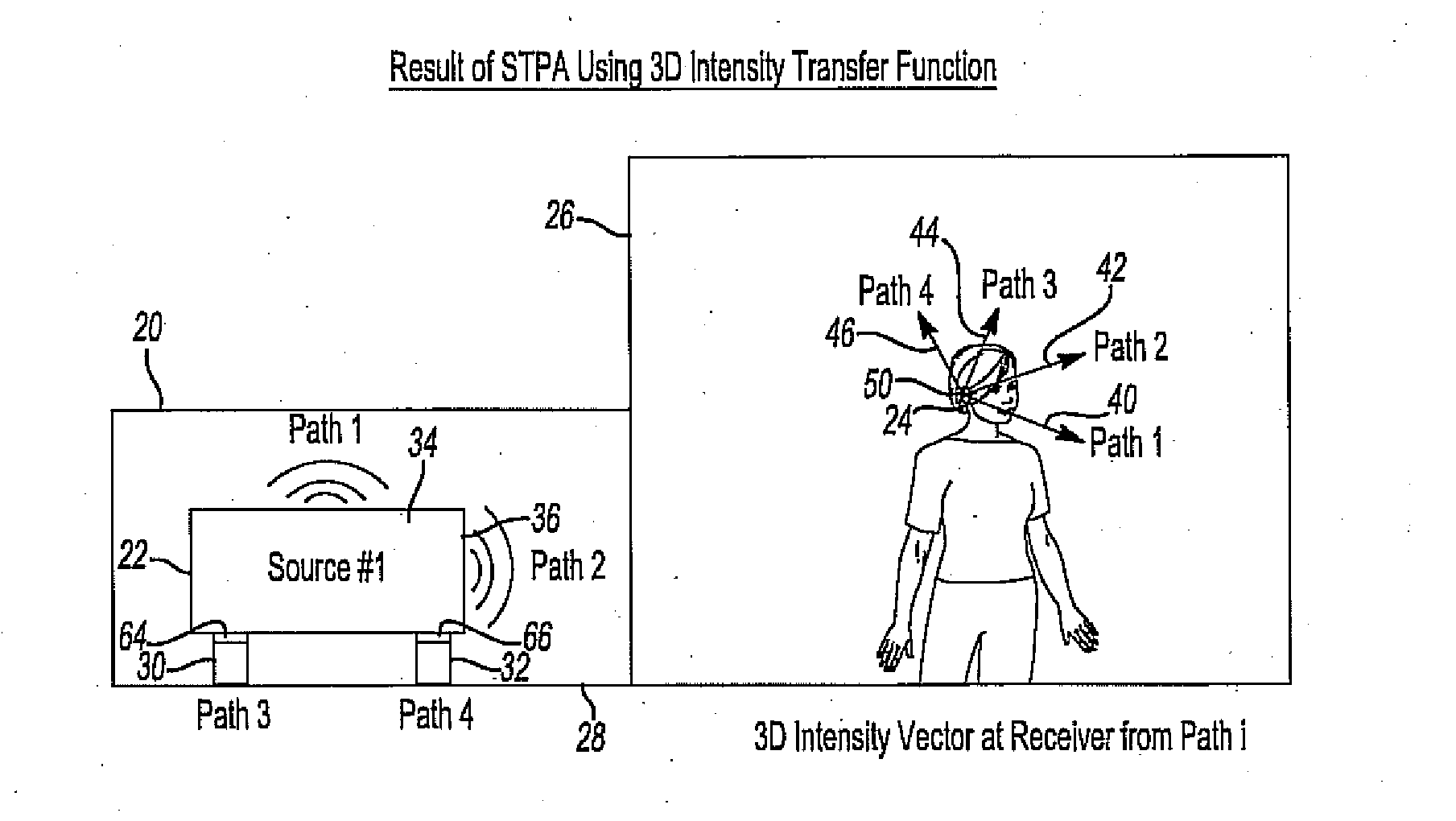
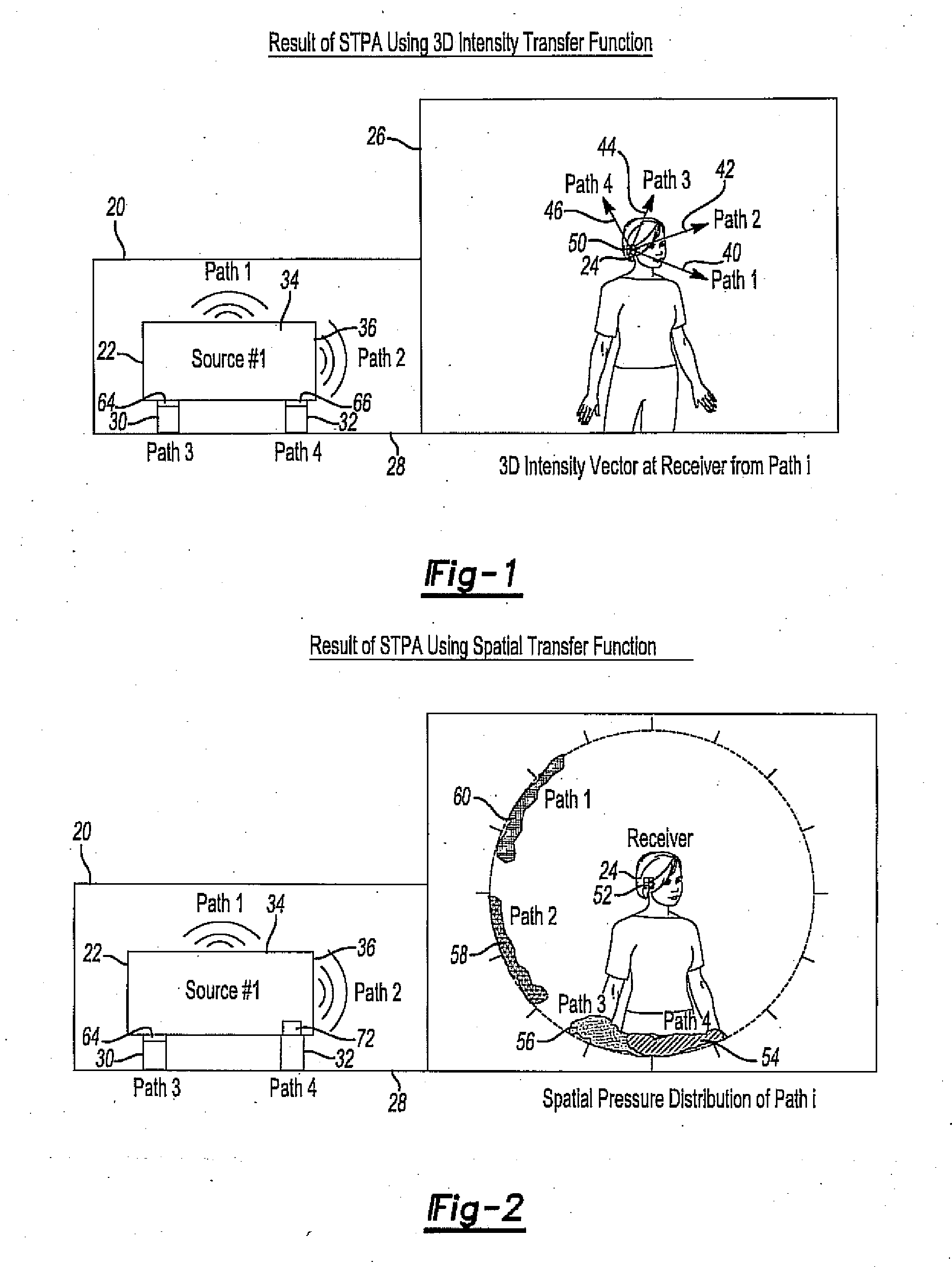
[0020]With reference first to FIG. 1, a sound transmission system, such as an automobile, is illustrated diagrammatically. Although the system of FIG. 1 is illustrated as an automotive vehicle 20, it is to be understood that the present invention is not limited to the sound analysis for an automotive vehicle but rather applies to any sound system with multiple sound transmission paths. Consequently, the automotive vehicle 20 shown in FIG. 1 is for illustration purposes only.

[0021]The vehicle 20 includes a sound source 22, such as a vehicle engine, which generates noise (sound) during operation. That noise is received by a receiver 24, e.g. a vehicle passenger, in the passenger compartment 26. Ideally, minimization, or at least reduction, of the noise (sound) received by the receiver 24 is desired.

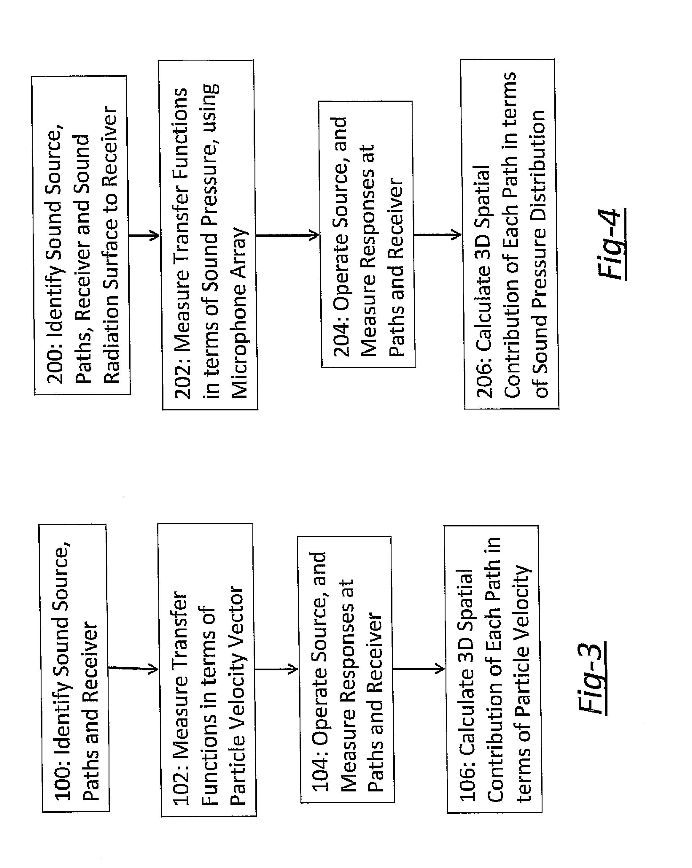
[0022]In the sound transmission analysis method of the present invention, each sound pathway from the sound source 22 and to the receiver 24 is first identified. The sound paths include bot...


PUM


Abstract

A method for analyzing sound transmission paths in a system from a sound source to a receiver in which the all sound paths are first identified from the sound source to the receiver. These sound paths include both structure-borne sound paths and air-borne sound paths. The transfer function from each path to the receiver is measured in terms of particle velocity vector by using a particle velocity sensor or a set of sound pressures by using a microphone array. The load at each path is directly measured or indirectly estimated in the actual source operation. The load at each path is multiplied by the transfer function from the path to the receiver, which represents the contribution of the path to the response at the receiver.

Description

BACKGROUND OF THE INVENTION[0001]I. Field of the Invention[0002]The present invention relates to a method for analyzing sound transmissions in a system from a sound source to a receiver.[0003]II. Description of Related Art[0004]Transfer path analysis (TPA) is a technique for comparing the sound transmission paths in a system from the sound source and to a receiver. TPA is particularly useful in automotive applications to compare the sound transmission paths between the various sound sources, such as the engine, transmission, etc., and the receiver, typically a user's ears in the passenger compartment.[0005]In the previously known applications of TPA for automotive systems, each sound path between the sound source and the receiver is first identified. The sound transmission paths, furthermore, include both structure-borne sound paths and air-borne sound paths. For example, structure-borne sound paths would include the sound path from a sound source, such as the engine, through the en...

Claims


Application Information

Patent Timeline
Patent Type & Authority Applications(United States)
IPC IPC(8): H04R29/00
CPCG01S3/80G01H3/00
Inventor INOUE, AKIRATANABE, YOSUKE
Owner HITACHI LTD
Why Eureka
Try Eureka