
Synthetic bone model and method for providing same

a bone model and synthesizer technology, applied in the field of synthesized bone models, can solve the problems of relatively expensive and/or time-consuming acquisition of “sawbone” models, especially custom versions

Inactive Publication Date: 2013-04-04
THE CLEVELAND CLINIC FOUND
View PDF5 Cites 117 Cited by
  • Summary
  • Abstract
  • Description
  • Claims
  • Application Information

AI Technical Summary

Benefits of technology

The patent describes a method for creating a synthetic bone model that can be used for bone replacement or research. The method involves extracting data from a 3D scan of a person's bone, creating an outer shell of the bone using a 3D printer, and adding a filler material to the inner cavity of the bone. The result is a precise and customizable model of a person's own bone that can be used for research or replacement.

Problems solved by technology

However, “Sawbones” models, particularly custom versions, can be relatively expensive and / or time-consuming to obtain.

Method used


Image

  • Synthetic bone model and method for providing same
  • Synthetic bone model and method for providing same
  • Synthetic bone model and method for providing same

Examples


Embodiment Construction

[0012]An example subject bone is shown and described herein at least as a scapula or portion thereof, but the subject bone could be any desired types such as, but not limited to, hip joints, shoulder joints, knee joints, ankle joints, phalangeal joints, metatarsal joints, spinal structures, long bones (e.g., fracture sites), or any other suitable patient tissue use environment for the present invention.

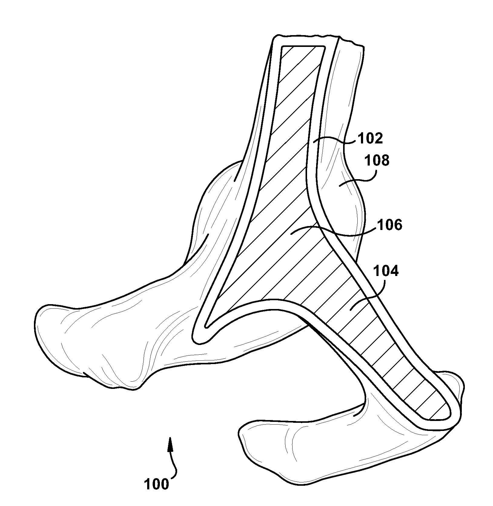
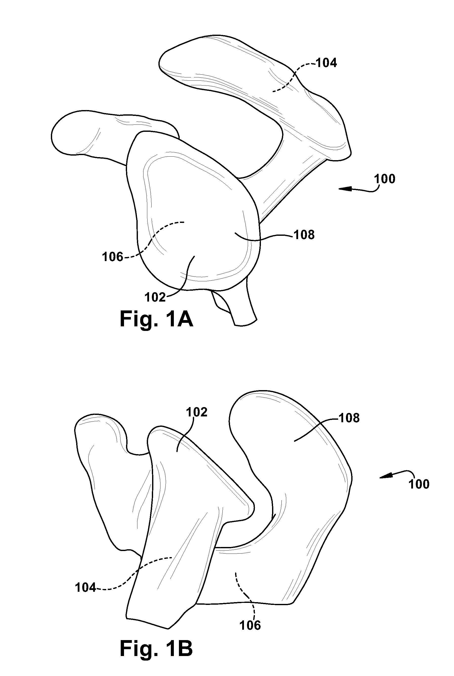
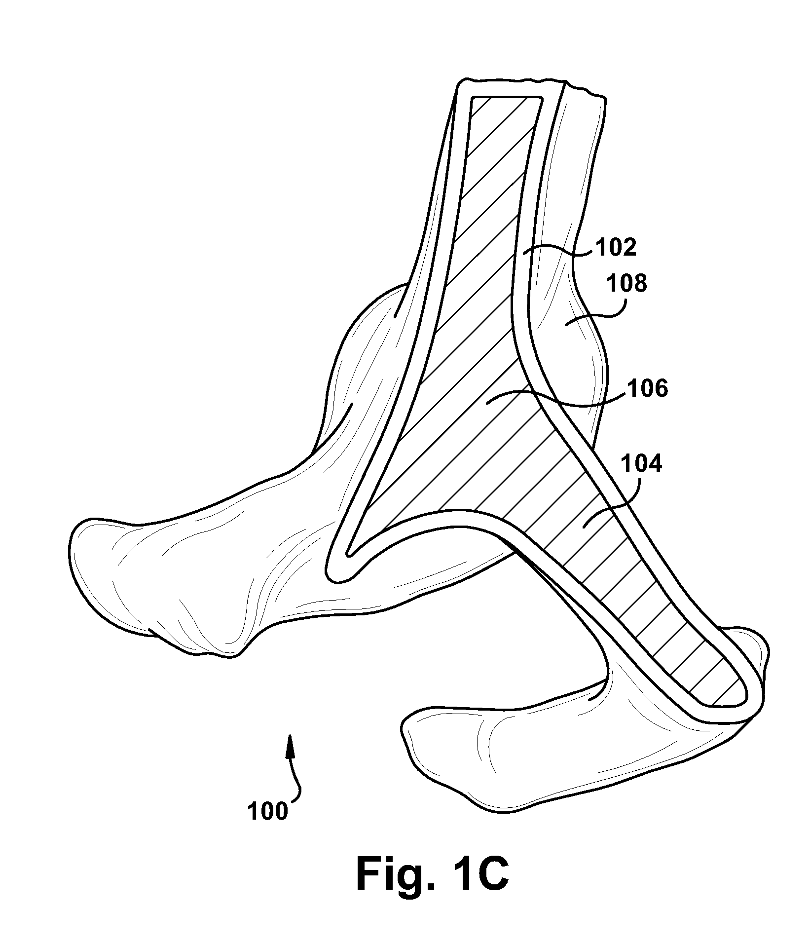
[0013]In accordance with the present invention, FIGS. 1A-1C depict a synthetic bone model 100. The synthetic bone model 100 includes a thin-walled outer shell 102, which is formed by a manufacturing device directly from manufacturing instructions. The manufacturing device implementing the manufacturing instructions could be a rapid prototyping device, which is a type of machine that can take manufacturing instructions from a computer and responsively create a structure from raw material(s). A rapid prototyping device is a different type of construction technology than, for example, a ...


PUM


Abstract

A method for providing a synthetic bone model of a subject bone includes providing a file with data representing a three-dimensional subject bone. Manufacturing instructions are generated based upon at least a portion of the data. The manufacturing instructions are transferred to a manufacturing device. A thin-walled outer shell of the synthetic bone model is created directly from the manufacturing instructions using the manufacturing device. The outer shell defines an inner cavity. A filler material is placed within at least a portion of the inner cavity. A synthetic bone model is also disclosed.

Description

RELATED APPLICATION[0001]This application claims priority from U.S. Provisional Application No. 61 / 542,605, filed 3 Oct. 2011, the subject matter of which is incorporated herein by reference in its entirety.TECHNICAL FIELD[0002]The present invention relates to a modeling method and system and, more particularly, to a synthetic bone model and a method for providing same.BACKGROUND OF THE INVENTION[0003]It is common in the surgical setting to machine or modify patient tissue to permit use of internal screws for fixation of fractures, to implant artificial joints, to fix intramedullary implants, for arthroplasty purposes, and to facilitate various other surgical procedures. These surgical procedures involve precise machining of sensitive tissues. Particularly when the surgical procedure is an unusual or complex one, or the patient's tissue structure includes abnormalities (whether congenital or acquired), the surgeon may wish to rehearse or refine the surgical procedure in advance on a...

Claims


Application Information

Patent Timeline
Patent Type & Authority Applications(United States)
IPC IPC(8): G06F17/50
CPCG09B23/30B33Y80/00
Inventor BRYAN, JASON A.KLATTE, RYAN S.O'NEILL, PETER D.
Owner THE CLEVELAND CLINIC FOUND
Learn More