Medical linear accelerator signal analyzer and display device

a linear accelerator and signal analyzer technology, applied in the field of linear accelerators, can solve the problems of linear accelerators being subject to decreased efficiency or malfunction, damage or defects, and linear accelerators being vulnerable to defective or compromised power sources

Active Publication Date: 2013-04-04
VARIAN MEDICAL SYSTEMS
View PDF21 Cites 2 Cited by
  • Summary
  • Abstract
  • Description
  • Claims
  • Application Information

AI Technical Summary

Benefits of technology

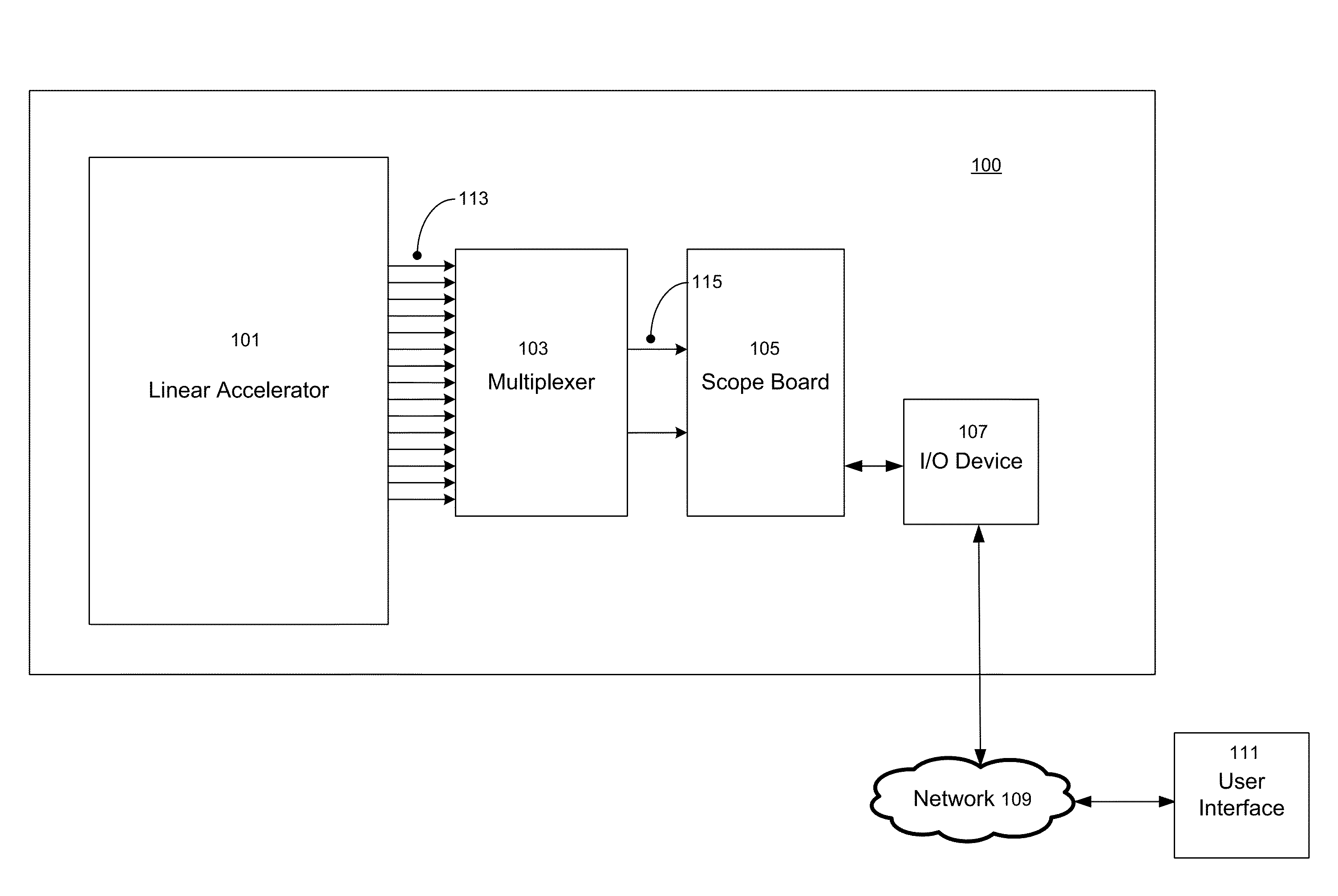
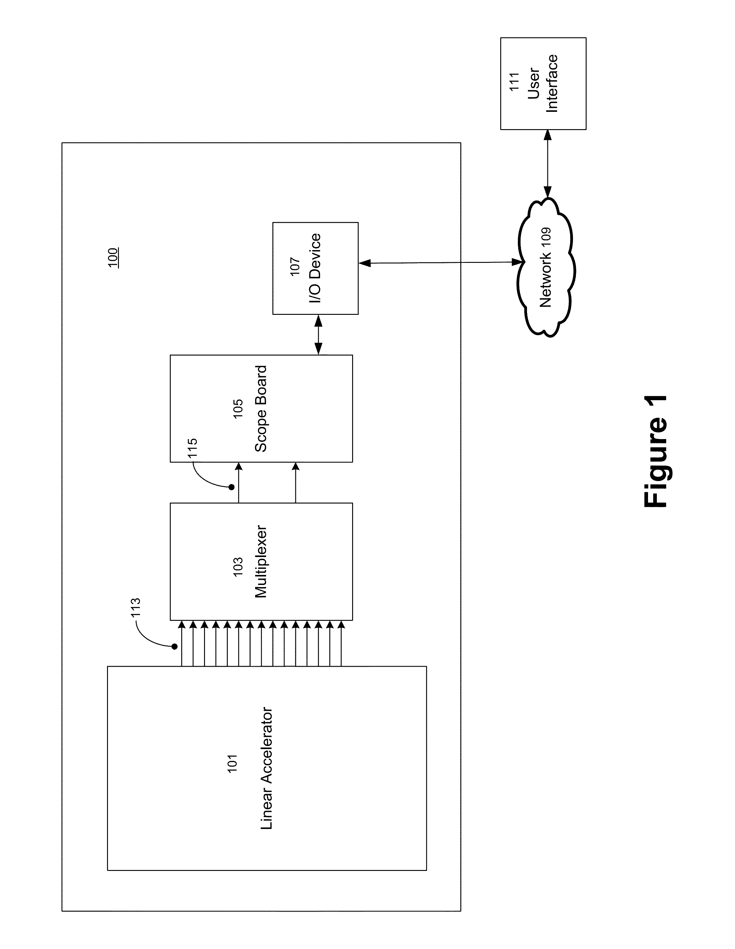
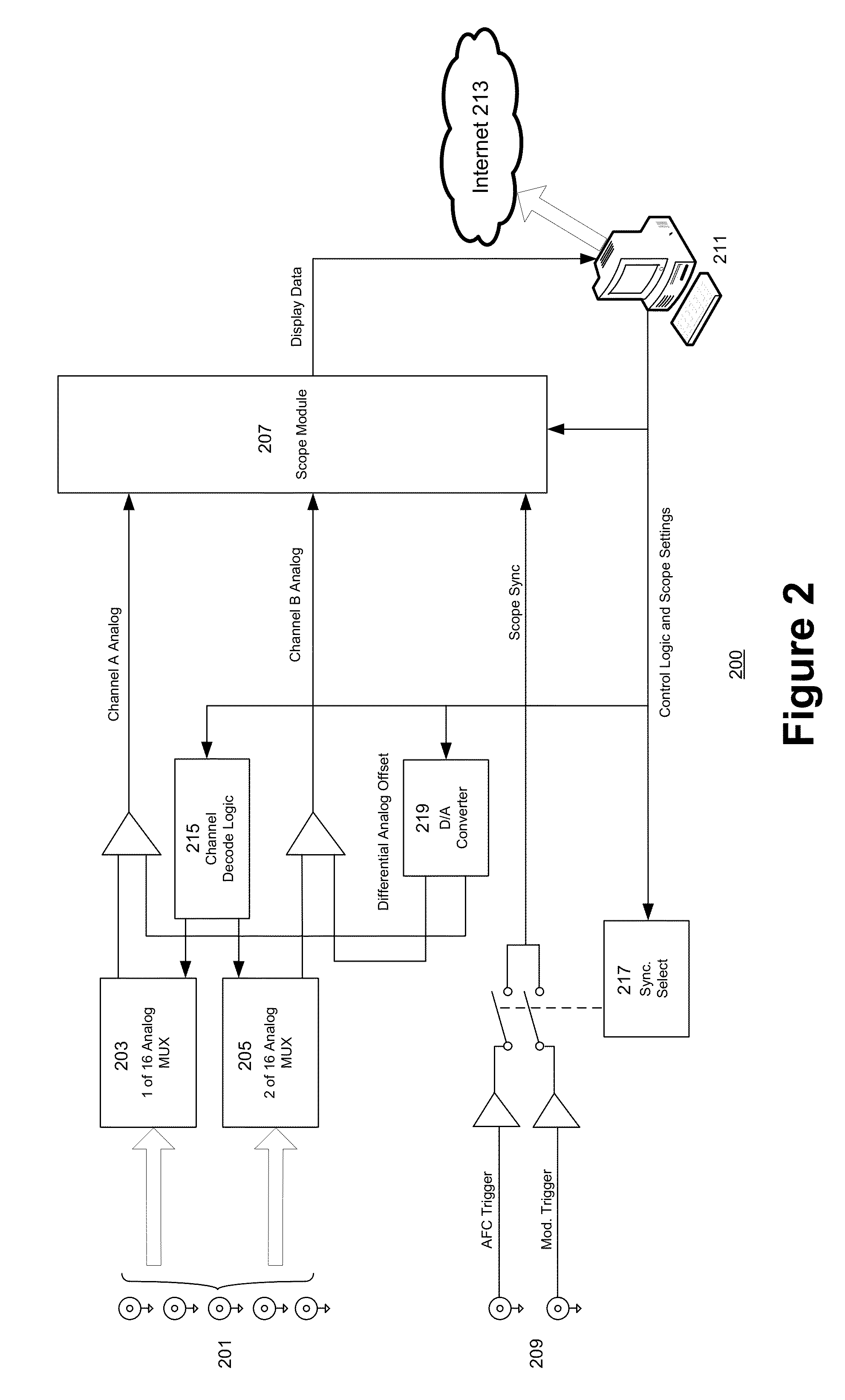
[0006]The multiplexer then outputs the signal data corresponding to the user-selected channels into a scope board which formats the signal data (analog) into digital display data. In still further embodiments, the scope board is coupled to an input / output communications device, such as a computing device configured to connect to a network, such as a local area network (LAN), wide area network (WAN), or the Internet. The display data is accessible to instances of an associated user interface executing on a remotely located computing system through the network. According to one embodiment, a remote computing system may be required to successfully complete an authorization protocol to access the display data on the communications device. Thereafter, the display data may be graphically represented on a display device coupled to the computing system. In still further embodiments, the user is able to select a different set of signal channels, and / or manipulate a plurality of control operations to modify display parameters to reformat the display data as desired through the instance of the user interface. For selections of signal channels, the user input is relayed to the multiplexer, which automatically conforms (i.e., selects) the output according to the user selection. Likewise, for modifications to display parameters, the user input is relayed to the scope board which automatically reformats the signal data into display data according to the display parameters. Accordingly, such a system allows an emulation of troubleshooting via on-site diagnosis with an oscilloscope through remote, secure interfaces, while avoiding the traditional requirements of on-site proximity and / or manual adjustment of probed sites.

Problems solved by technology

However, like many other complex systems, linear accelerators are subject to decreased efficiency or malfunction due to various causes.
These causes may include, for example, damage or defects attributable to malfunctioning subcomponents or environmental factors.
For example, as heavy consumers of electrical power, medical linear accelerators may be vulnerable to defective or compromised power sources.
This may result in ineffective or inefficient operation of the linear accelerator.
Unfortunately, typical oscilloscopes are equipped with only a few (e.g., two or four) probe devices.
Oscilloscopes with even greater probes are exponentially more expensive.
This requires that the field service representative manually reposition the oscilloscope probes to correspond to the areas of interest for each area of interest in excess of the number of probes, or sacrifice tremendous cost-effectiveness.
Naturally, this can be an extremely user intensive process due to the effort and expertise required to manually reposition the oscilloscope probes.
Even with more expensive oscilloscopes, such practice can result in significant delays—particularly to remote linear accelerators—due to the time required to travel to the linear accelerator site, and even then, connecting each probe to the areas of interest for each service operation—and each linear accelerator—can result in extremely compromised efficiency.

Method used


Image

  • Medical linear accelerator signal analyzer and display device
  • Medical linear accelerator signal analyzer and display device
  • Medical linear accelerator signal analyzer and display device

Examples


Embodiment Construction

[0015]Reference will now be made in detail to several embodiments. While the subject matter will be described in conjunction with the alternative embodiments, it will be understood that they are not intended to limit the claimed subject matter to these embodiments. On the contrary, the claimed subject matter is intended to cover alternative, modifications, and equivalents, which may be included within the spirit and scope of the claimed subject matter as defined by the appended claims.

[0016]Furthermore, in the following detailed description, numerous specific details are set forth in order to provide a thorough understanding of the claimed subject matter. However, it will be recognized by one skilled in the art that embodiments may be practiced without these specific details or with equivalents thereof. In other instances, well-known processes, procedures, components, and circuits have not been described in detail as not to unnecessarily obscure aspects and features of the subject m...


PUM


Abstract

A method and system is proposed for providing automated, electronic testing of a linear accelerator from a remote position. According to one aspect of the claimed subject matter, a system is described which includes a linear accelerator with a scope circuit board, a multiplexer printed circuit board and a computing device. The multiplexer printed circuit board is coupled to the linear accelerator at a plurality of signal sites or locations corresponding to common areas of interest. Signal data received by the multiplexer circuit board may be continuously streamed from the linear accelerator to the multiplexer through each “channel” of data. The multiplexer circuit board is configured to receive, as input, the data corresponding to the electrical activity. In a further embodiment, the multiplexer outputs a selection of signals corresponding to a user selection of one or more channels from a remote terminal.

Description

TECHNICAL BACKGROUND[0001]The development of medical linear accelerators (linacs) has dramatically increased the practicality and efficiency of multi-field radiation therapy treatments. However, like many other complex systems, linear accelerators are subject to decreased efficiency or malfunction due to various causes. These causes may include, for example, damage or defects attributable to malfunctioning subcomponents or environmental factors. For example, as heavy consumers of electrical power, medical linear accelerators may be vulnerable to defective or compromised power sources. This may result in ineffective or inefficient operation of the linear accelerator.[0002]Traditional methods of diagnosing and solving such problems, known as “troubleshooting,” often include usage of an oscilloscope. Oscilloscopes are a type of electronic test instrument which, when coupled (via probes) to an area exhibiting radio frequency or electrical activity (e.g., with an electric current, freque...

Claims


Application Information

Patent Timeline
Patent Type & Authority Applications(United States)
IPC IPC(8): H05H9/00G06F19/00
CPCH05H2277/11H05H9/00G21K1/12A61N5/1075A61N5/1048
Inventor BURTON, BRADLEYMALLIA, PIERREBROWN, JAY
Owner VARIAN MEDICAL SYSTEMS
Why Eureka
Try Eureka