Robot cleaner

Active Publication Date: 2013-04-11
SAMSUNG ELECTRONICS CO LTD
View PDF4 Cites 103 Cited by
  • Summary
  • Abstract
  • Description
  • Claims
  • Application Information

AI Technical Summary

Benefits of technology

[0033]The brush guide may be pivoted and inserted into the main body even if the protruding

Problems solved by technology

However, the side brush could not be fabricated longer than a predetermined length because it is required to impede traveling of the robot cleaner and to not cause interference with other elements arr

Method used


Image

  • Robot cleaner
  • Robot cleaner
  • Robot cleaner

Examples


Embodiment Construction

[0054]Reference will now be made in detail to the embodiments of the present disclosure, examples of which are illustrated in the accompanying drawings, wherein like reference numerals refer to like elements throughout.

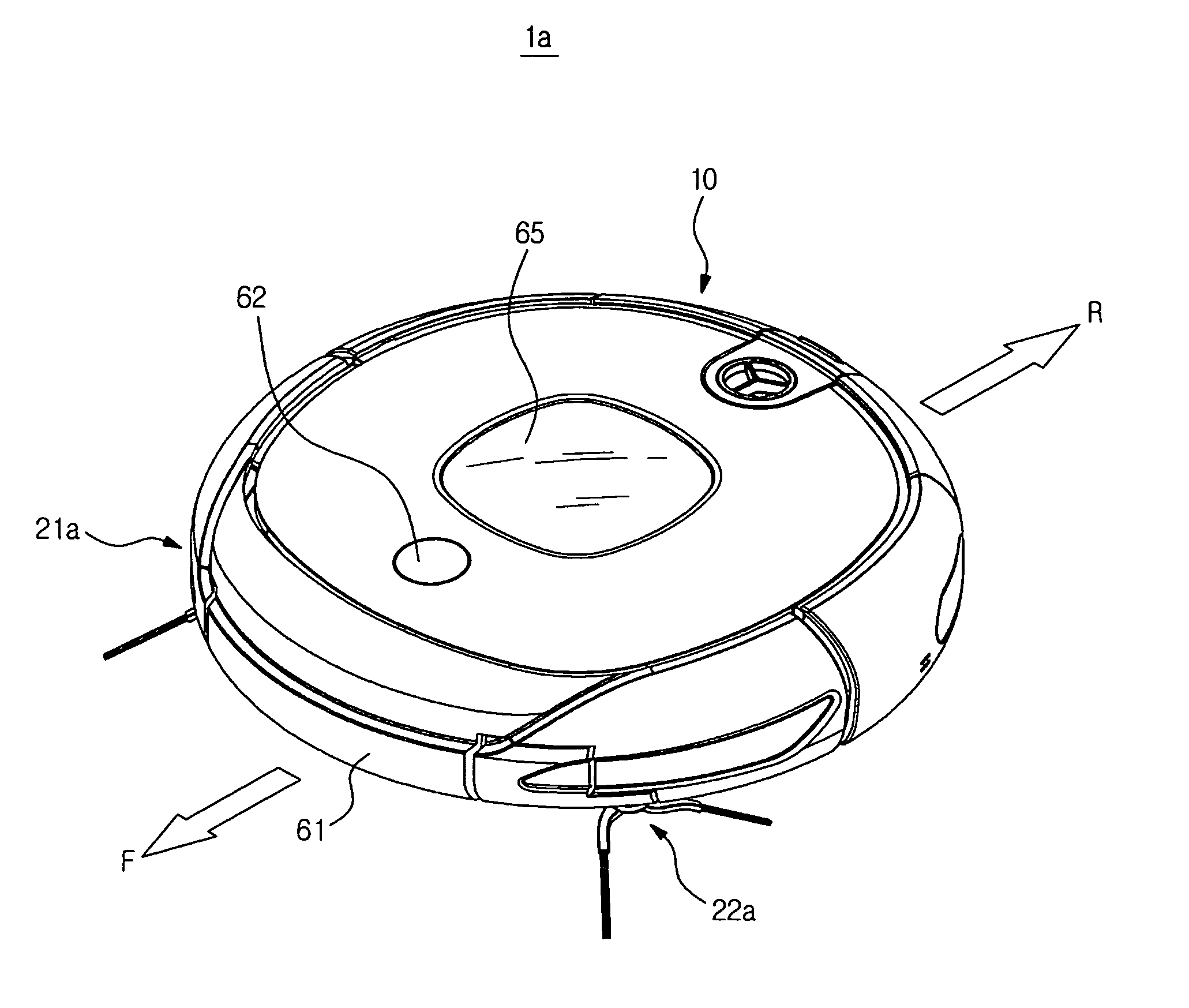
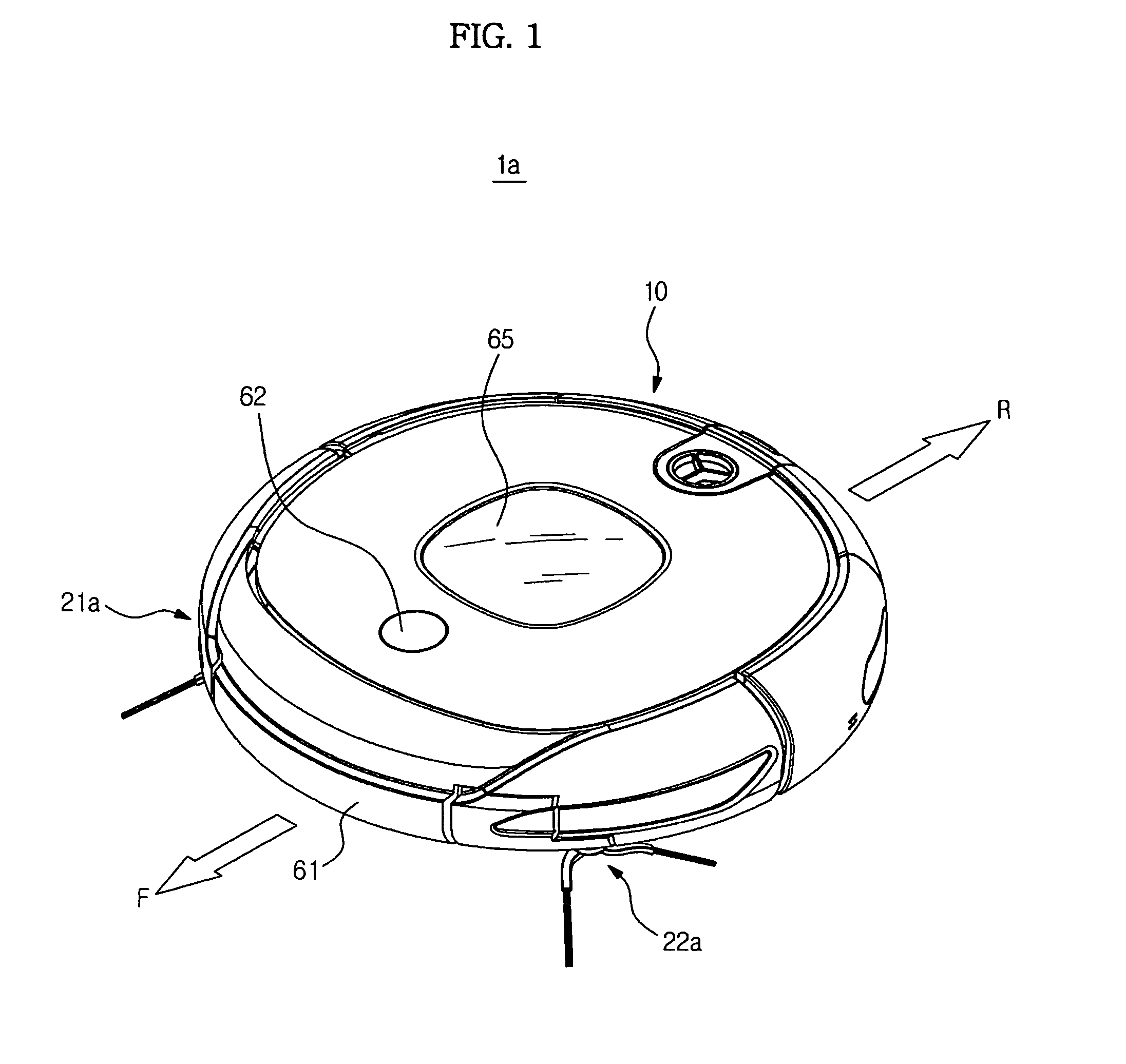
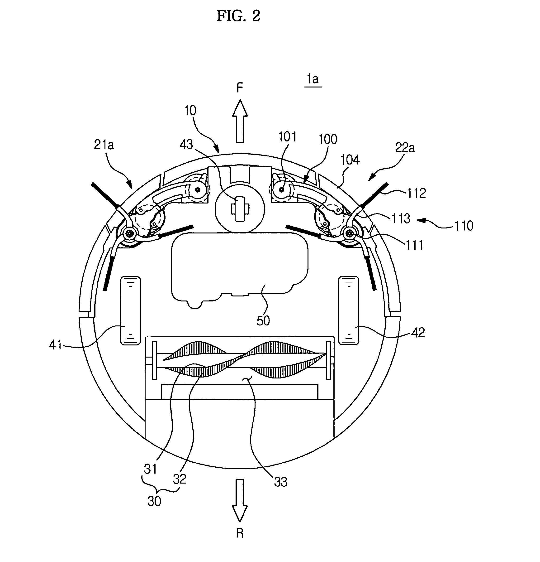
[0055]As shown in FIGS. 1 and 2, a robot cleaner 1a includes a main body 10 forming the external appearance of the robot cleaner 1 a, a main brush unit 30 configured to sweep dust present on a floor and direct the dust to a suction opening, a power unit 50 to supply power required to move the main body 10, drive wheels 41 and 42 and a caster 43 for movement of the main body 10, and side brush assemblies 21a and 22a to clean an area close to the wall and the corner of the floor.

[0056]The two drive wheels 41 and 42 are symmetrically arranged at left and right edges of a bottom center region of the main body 10. These drive wheels enable movements of the main body 10 including, for example, forward and backward traveling and rotation traveling during cleaning.

[0057]The c...


PUM


Abstract

The robot cleaner includes a main body configured to remove dust from a floor while traveling on the floor, the main body having a lateral rim defining the external appearance of a lateral surface of the robot cleaner, and at least one side brush assembly mounted to the main body to clean the corner of the floor. The side brush assembly includes a side arm pivotably coupled to the main body, the side arm moving between a first position where the side arm is inserted into the main body and a second position where the side arm protrudes outward from the lateral rim of the main body, a brush unit provided at the side arm to sweep the floor, and a rim cover coupled to the side arm to form a part of the lateral rim of the main body when the side arm is inserted into the main body.

Description

CROSS-REFERENCE TO RELATED APPLICATIONS[0001]This application claims the benefit of Korean Patent Application No. 10-2011-0101852, filed on Oct. 6, 2011 in the Korean Intellectual Property Office, the disclosure of which is incorporated herein by reference.BACKGROUND[0002]1. Field[0003]Embodiments of the present disclosure relate to a robot cleaner to achieve enhanced cleaning performance at an area close to the wall or at the corner of the floor.[0004]2. Description of the Related Art[0005]A cleaner is an apparatus that cleans a room by removing impurities. In recent years, a robot cleaner, which removes impurities from an indoor floor while autonomously moving via an automated traveling function without user intervention, has been actively developed.[0006]More specifically, the robot cleaner is adapted to automatically clean a target area by sucking up impurities, such as dust, from a floor while autonomously traveling about the area to be cleaned without user manipulation.[0007]T...

Claims


Application Information

Patent Timeline
IPC IPC(8): A47L11/24A47L11/40
CPCA47L11/24A47L11/4069A47L9/0488A47L2201/00A47L11/4055A47L11/4058A47L11/4061A47L11/4038A47L5/12A47L9/04A47L9/0411A47L9/0461A47L9/00A47L11/40A47L9/28A47L11/20A47L11/4036
Inventor HAN, SEUNG ILKIM, DONG WONYOON, SANG SIKLEE, JUN HWAJANG, HWI CHAN
Owner SAMSUNG ELECTRONICS CO LTD
Why Eureka
Try Eureka