Burner apparatus, submerged combustion melters including the burner, and methods of use
a technology of burners and submerged combustion melters, which is applied in the direction of lighting and heating apparatus, combustion types, manufacturing tools, etc., can solve problems such as inability to easily modify
- Summary
- Abstract
- Description
- Claims
- Application Information
AI Technical Summary
Benefits of technology
Problems solved by technology
Method used
Image
Examples
embodiment 24
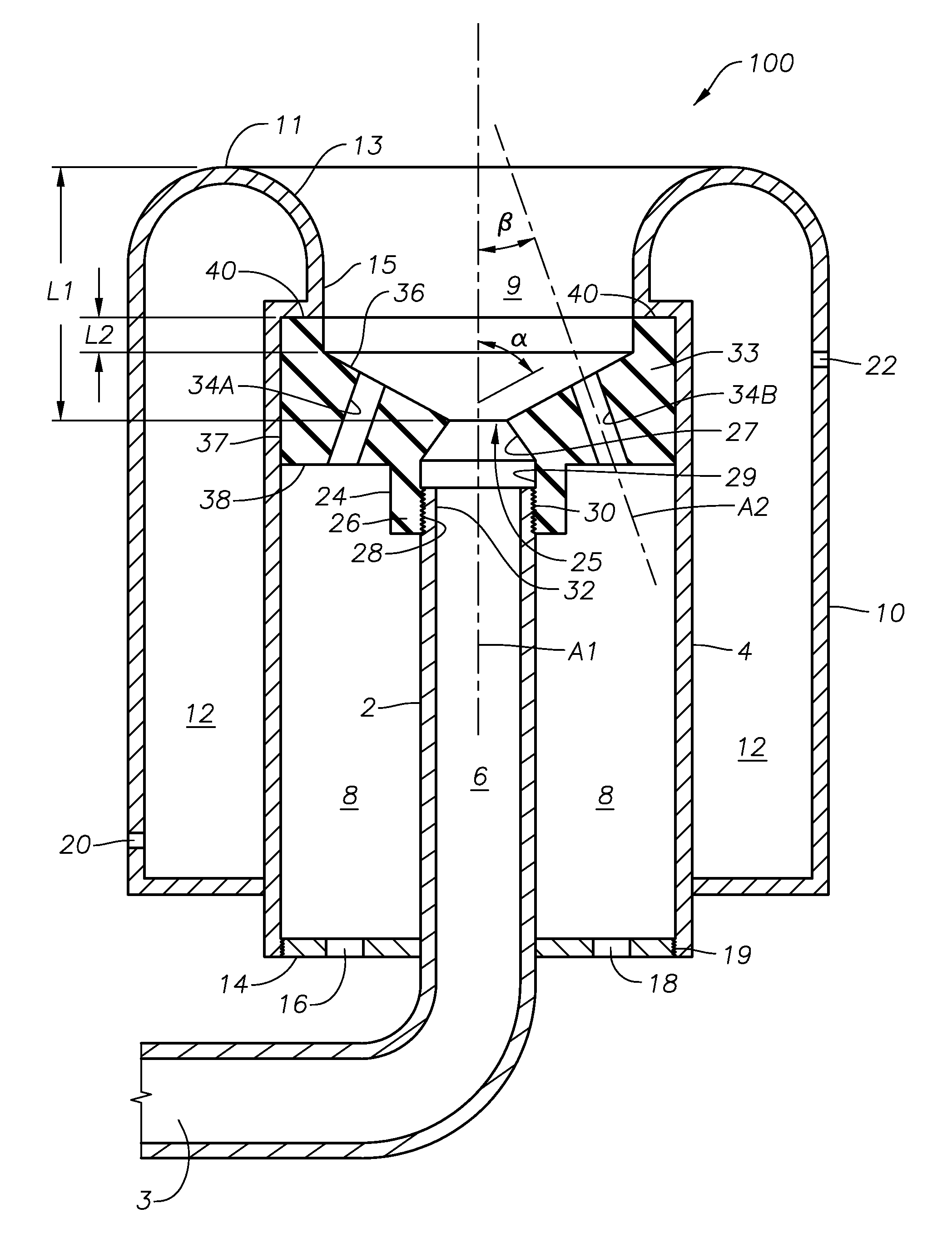
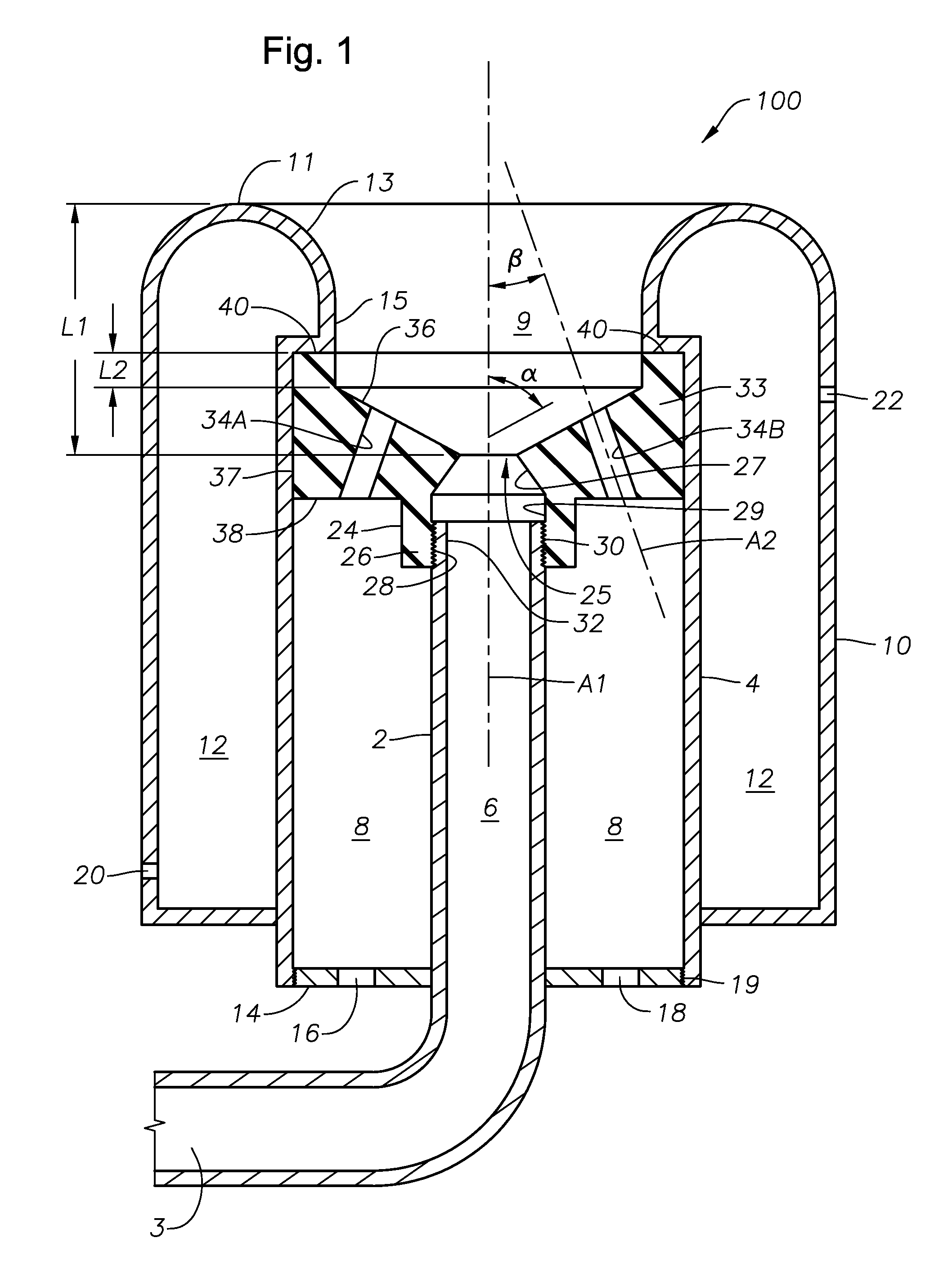
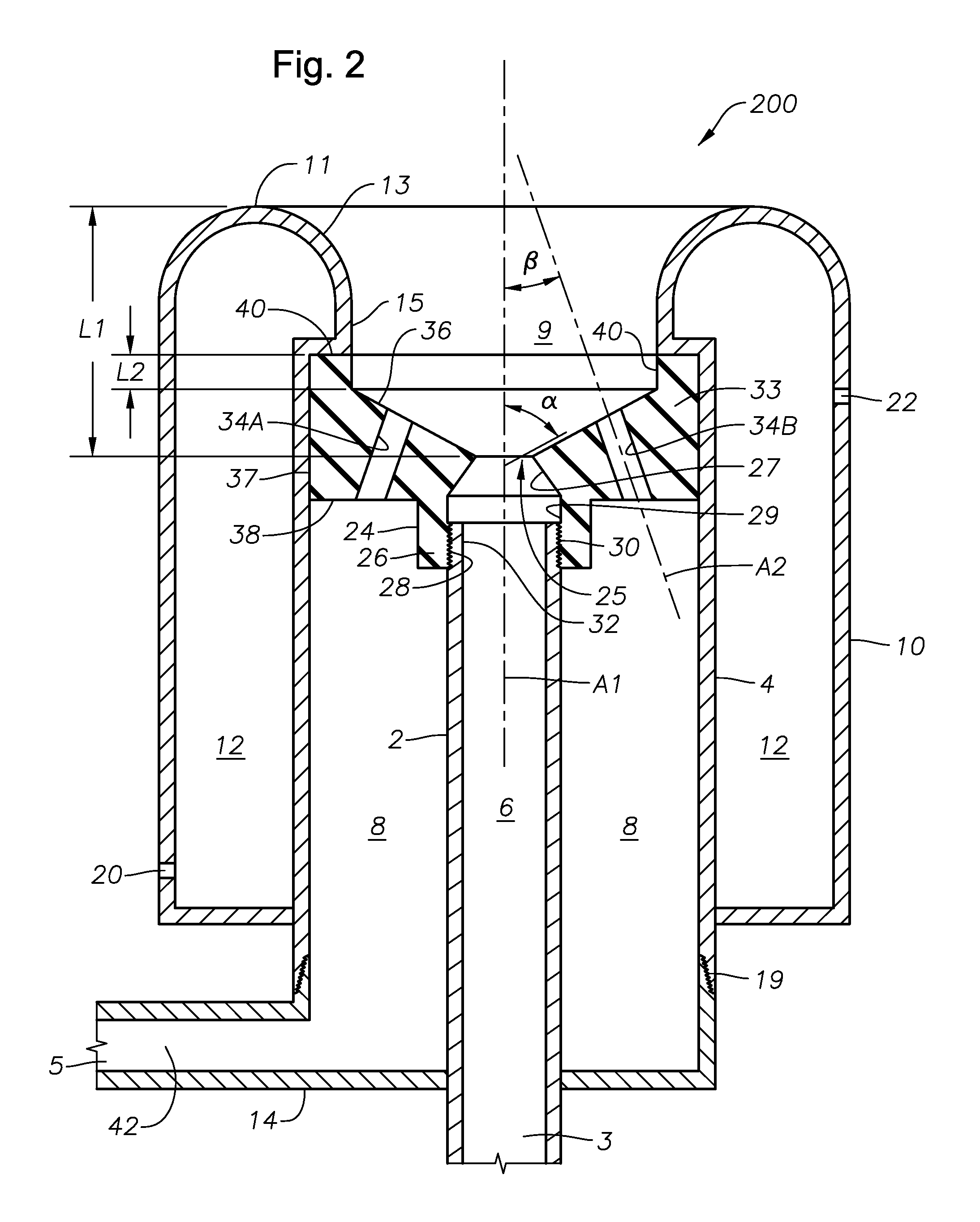
[0054]FIG. 3A is a cross-sectional view of embodiment 24 of an adjustable, removable component of the burners of FIGS. 1 and 2 taken along the line A-A of FIG. 3B, which is a plan view of the same embodiment.
embodiment 50
[0055]FIGS. 4 and 5 are cross-sectional views of two other embodiments of adjustable, removable burner components of the present disclosure. As illustrated schematically in embodiment 50 of FIG. 4, the non-central passages may comprise a vertical section 44A, 44B, and an angled section 46A, 46B. Vertical section 44A, 44B begins at lower surface 38 of body 24 and intersects angled section 46A, 46B, respectively, in body 24 at position 47A, 47B, which may vary from burner to burner in accordance with the present disclosure. Angled section 46A, 46B ends at upper surface 36 of body 24. Another optional feature of burners of the present disclosure is a vertical extension 31 connecting angled section 27 with exit 25. The length of vertical section 31, designated L5, may be another feature of burners of the present disclosure that may be changed to affect burner operation. L5 may range from 0 to about 3 inches, or from about 0.25 to about 2 inches.
[0056]In embodiment 60 illustrated schemat...
embodiment 70
[0057]FIG. 6 is a side-elevation view, partially in cross-section, of a submerged combustion melter embodiment 70 in accordance with the present disclosure, positioned on a plant floor or other surface 72, including two burners 200A and 200B of the disclosure. More than or less than two burners of the present disclosure may be used, as well as burners of other designs, as long as one burner of the present disclosure is present. Metter 70 includes sidewalls 78, a floor 80, a roof 82, an exhaust chute 76, and a glass melt exit 92. A glass-forming material feed bin 74 may be attached to melter sidewall 78. One or more burners 200 may be in one or more sidewalls 78, as long as the flame and / or products of combustion emanate below surface 91 of melt 90. Burners 200 may be positioned in a sidewalls 78 or floor 80 of a submerged combustion melter apparatus such that the longitudinal axis A1 (FIGS. 1-3) makes an angle to the side panel 78 or floor 80 of the melter ranging from about 30 to a...
PUM
| Property | Measurement | Unit |
|---|---|---|
| β angle | aaaaa | aaaaa |
| distance L1 | aaaaa | aaaaa |
| length L2 | aaaaa | aaaaa |
Abstract
Description
Claims
Application Information
 - R&D
- Intellectual Property
- Life Sciences
- Materials
- Tech Scout
- Unparalleled Data Quality
- Higher Quality Content
- 60% Fewer Hallucinations
Browse by: Latest US Patents, China's latest patents, Technical Efficacy Thesaurus, Application Domain, Technology Topic, Popular Technical Reports.
© 2025 PatSnap. All rights reserved.Legal|Privacy policy|Modern Slavery Act Transparency Statement|Sitemap|About US| Contact US: help@patsnap.com


