Methods of using a submerged combustion melter to produce glass products

a technology of glass products and melters, which is applied in the direction of furnaces, instruments, tank furnaces, etc., can solve the problems of system vibration and/or oscillation, and achieve the effect of measurable vibration and/or oscillation

Active Publication Date: 2013-04-11
JOHNS MANVILLE CORP
View PDF3 Cites 80 Cited by
  • Summary
  • Abstract
  • Description
  • Claims
  • Application Information

AI Technical Summary

Benefits of technology

[0007]In accordance with the present disclosure, methods of using vibrations and / or oscillations of a submerged combustion melter are described that may allow predicting or tuning of one or more molten or finished glass parameters.

Problems solved by technology

The nature of submerged combustion melters and their operation cause a perceptible and measurable vibration and / or oscillation in the system.

Method used


Image

  • Methods of using a submerged combustion melter to produce glass products
  • Methods of using a submerged combustion melter to produce glass products
  • Methods of using a submerged combustion melter to produce glass products

Examples


embodiment 1

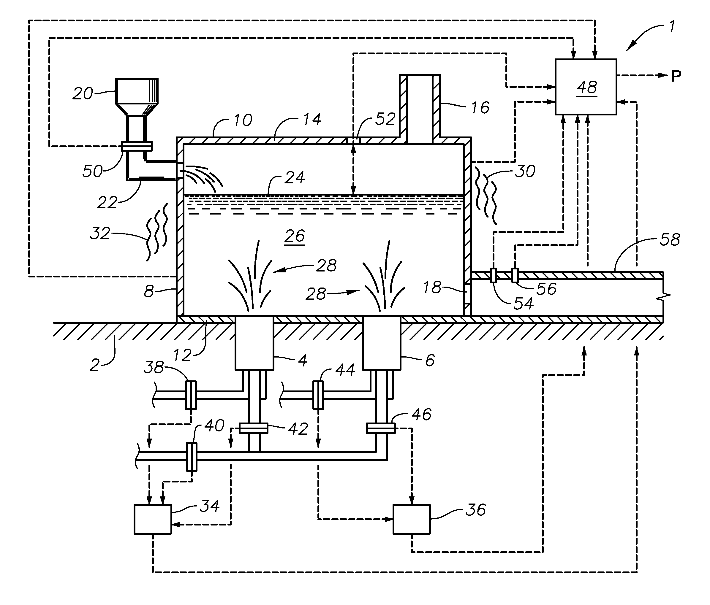
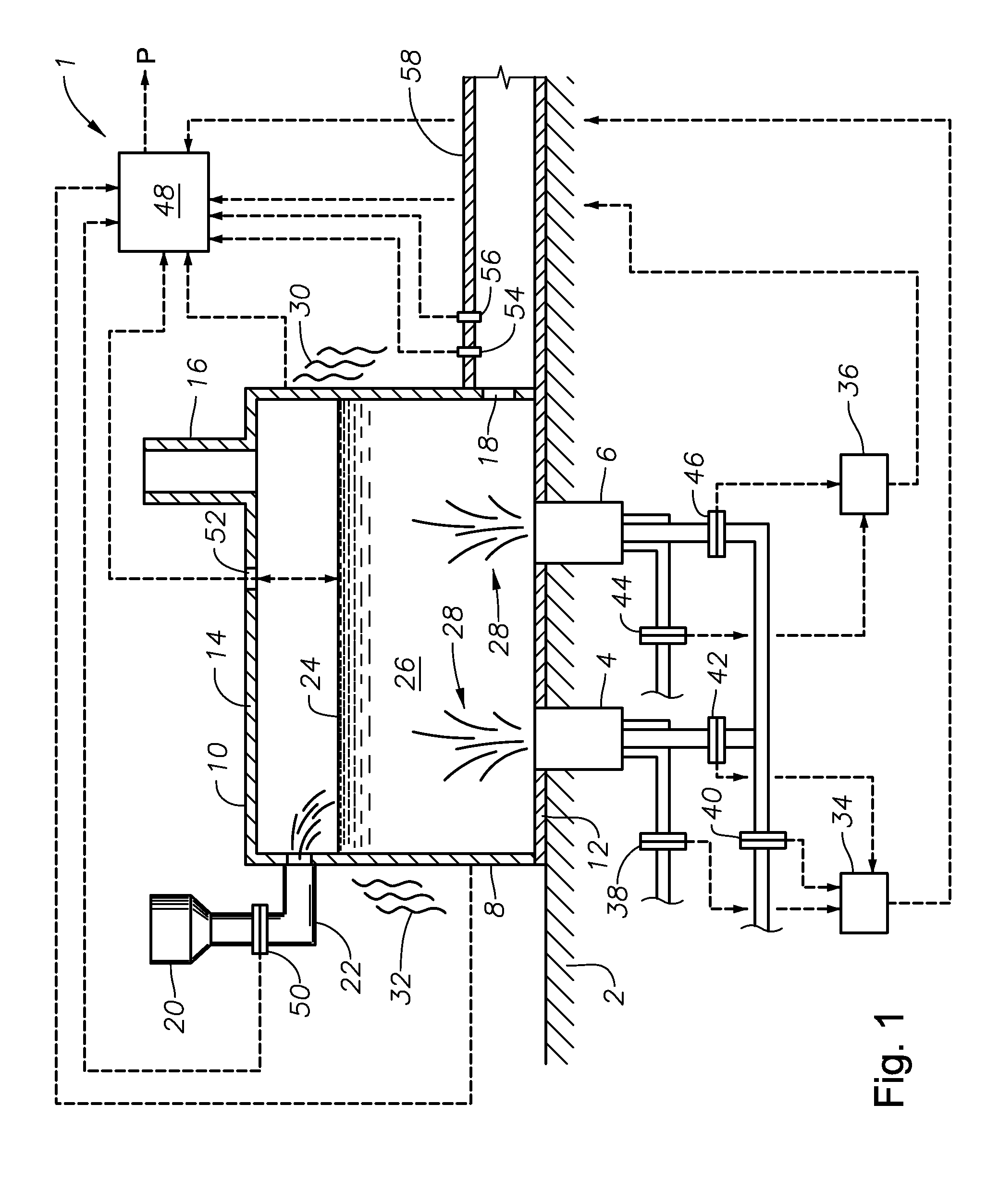
[0040]Referring now to the figures, FIG. 1 is a side-elevation view, partially in cross-section, of a submerged combustion melter system and method embodiment 1 in accordance with the present disclosure, including a glass tank furnace or melter 10 positioned on a plant floor or other surface 2, including two burners 4 and 6, one or both of which may be of the adjustable burner type described in assignee's co-pending U.S. patent application Ser. No. ______, filed ______ (JM 8054), comprising first and second conduits configured to form a primary annulus between the external surface of the first conduit and the internal surface of the second conduit, and an adjustable structure comprising a generally cylindrical central hub adjustable axially in relation to and removably attached to the first end of the first conduit, the hub defining a central passage and one or more non-central through passages. More than or less than two burners may be used, as well as burners of other designs, as ...

embodiment 500

[0053]FIGS. 5, 6, 7, and 8 are logic diagrams of four method embodiments in accordance with the present disclosure. The method of embodiment 500 of FIG. 5 comprises flowing an oxidant and a fuel into a submerged combustion burner in a glass tank furnace, the glass tank furnace also receiving a feed of glass forming material, the burner and furnace comprising a melting system, the melting system having a variable system vibration, the melting system producing molten glass, box 502; and predicting a value of at least one property of the molten glass using at least the variable system vibration, box 504.

[0054]Another method of this disclosure is presented in the logic diagram of FIG. 6 as embodiment 600. Embodiment 600 is a method of producing molten glass, and comprises the steps of flowing an oxidant and a fuel into at least one submerged combustion burner in a glass tank furnace, the glass tank furnace also receiving a feed of glass forming material, the burner and furnace comprisin...


PUM

PropertyMeasurementUnit
angleaaaaaaaaaa
diameteraaaaaaaaaa
diameteraaaaaaaaaa

Abstract

A method comprises flowing an oxidant and a fuel into a submerged combustion burner in a glass tank furnace, the glass tank furnace receiving a feed of glass forming material and producing molten glass, the burner and furnace comprising a melting system. The melting system has a variable system vibration and/or oscillation due to the nature of submerged combustion. One method includes predicting a value of at least one property, such as viscosity, of the molten glass using the variable system vibration and/or oscillation.

Description

CROSS-REFERENCE TO RELATED APPLICATIONS[0001]This application is related to assignee's U.S. non-provisional patent application Ser. No. 12 / 817,754, filed Jun. 17, 2010; Ser. No. 12 / 888,970, filed Sep. 23, 2010; Ser. No. ______, filed ______ (JM 8001); and Ser. No. ______, filed ______ (JM 8054), all of which are incorporated herein by reference.BACKGROUND INFORMATION[0002]1. Technical Field[0003]The present disclosure relates generally to the field of submerged combustion glass melters and methods of use.[0004]2. Background Art[0005]Submerged combustion melters are known for producing molten glass. The nature of submerged combustion melters and their operation cause a perceptible and measurable vibration and / or oscillation in the system.[0006]It would be an advance in the submerged combustion glass melting art to develop methods of using the vibration and / or oscillation of the submerged combustion melter, either alone or in combination with other system parameters, to predict proper...

Claims


Application Information

Patent Timeline
Patent Type & Authority Applications(United States)
IPC IPC(8): C03B5/24C03B37/07C03B5/04
CPCC03B37/06C03B37/07C03B37/02C03B5/24C03B19/08C03B5/2356C03B2211/22C03B2211/23Y02P40/50C03B5/04
Inventor CHARBONNEAU, MARK WILLIAMNESTI, BRYAN KEITH
Owner JOHNS MANVILLE CORP
Why Eureka
Try Eureka