Direct writing of functionalized acoustic backing

a technology of acoustic backing and writing method, which is applied in the direction of piezoelectric/electrostrictive transducers, generators/motors, mechanical vibration separation, etc., can solve the problem that acoustic transducers constructed using current methods typically encounter unmatched acoustic qualities between the transducer element and the acoustic backing

Active Publication Date: 2013-04-11
BAKER HUGHES INC
View PDF1 Cites 37 Cited by
  • Summary
  • Abstract
  • Description
  • Claims
  • Application Information

AI Technical Summary

Problems solved by technology

Acoustic transducers constructed using current methods typically encounter unmatched acoustic qualities between the transducer element and the acoustic backing.

Method used


Image

  • Direct writing of functionalized acoustic backing
  • Direct writing of functionalized acoustic backing
  • Direct writing of functionalized acoustic backing

Examples


Embodiment Construction

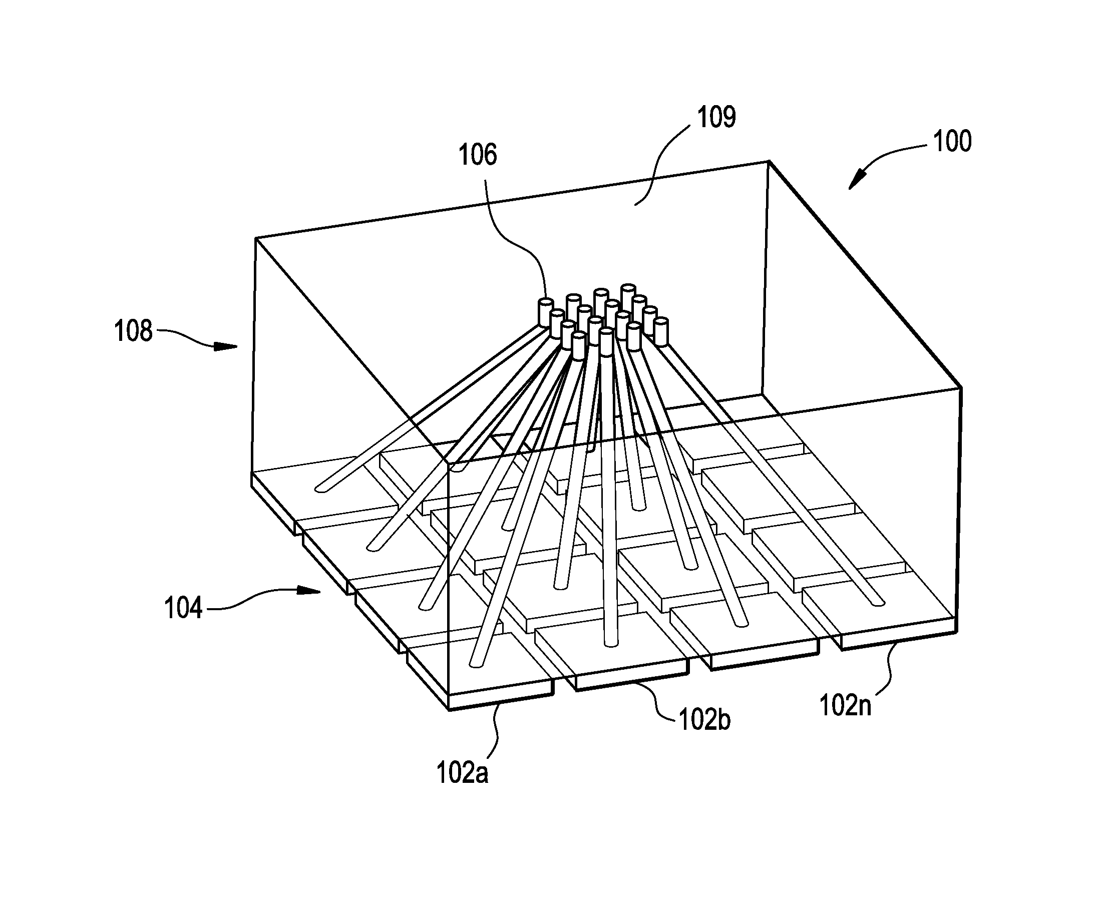
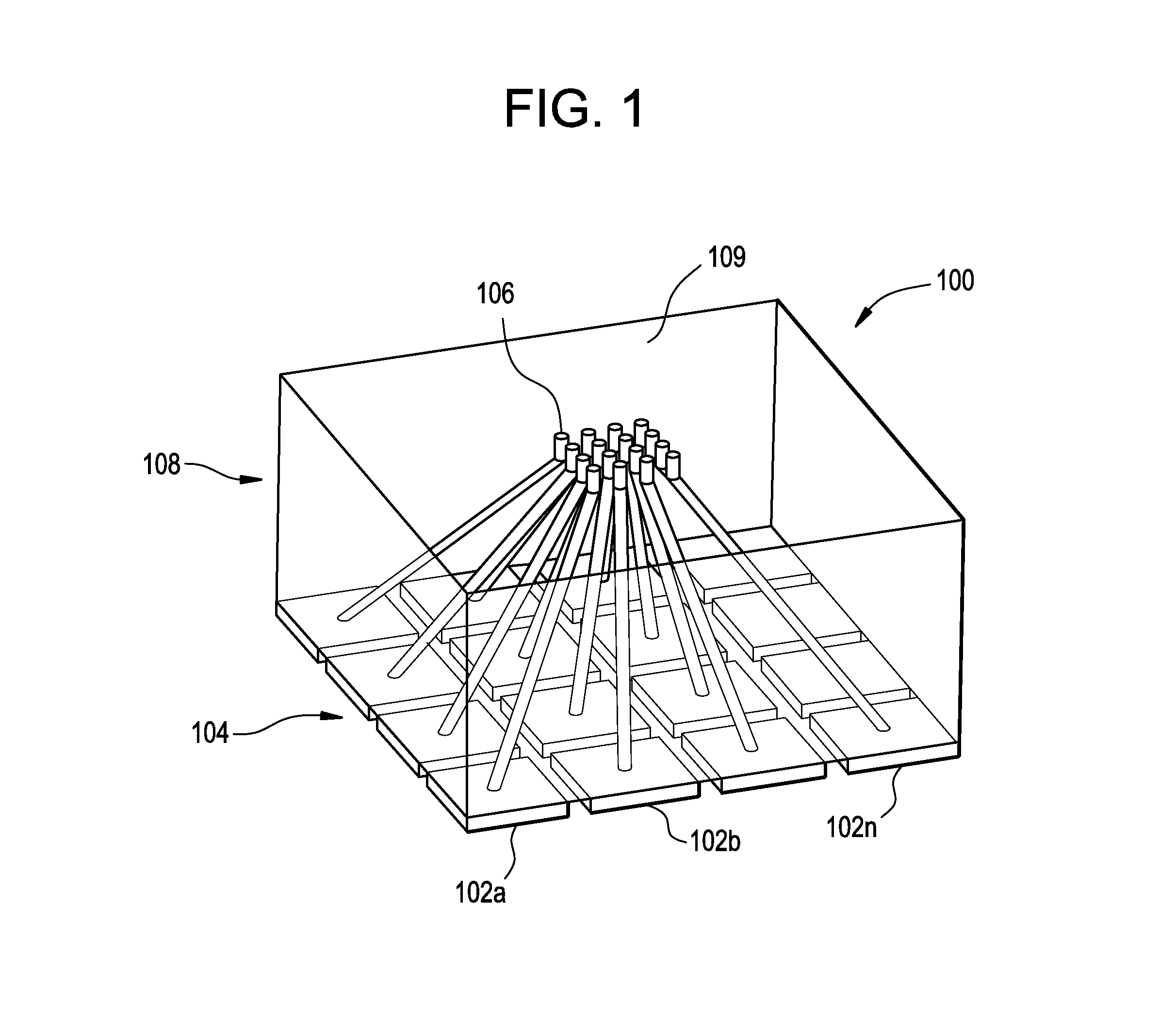
[0011]FIG. 1 shows an exemplary acoustic transducer 100 assembled using an exemplary method of the present disclosure. The exemplary acoustic transducer 100 includes a transducer layer 204 and an acoustic backing 108 coupled to the transducer layer 104. The transducer layer 104 includes one or more transducer elements 102a, 102b, . . . , 102n, which can be piezoelectric elements. The transducer elements 102a, 102b, . . . , 102n, are configured to receive an acoustic signal, which can include acoustic or ultrasonic signals, and generate an electrical signal in response to the received acoustic signal. Acoustic backing 108 includes backing material 109 configured to provide acoustic signal attenuation and one or more electrically conductive paths, such as exemplary path 106, for conducting the electrical signal generated at the transducer layer 104 to circuitry (not shown) for processing. In one embodiment, the one or more electrically conductive paths traverse an interior region of t...


PUM

PropertyMeasurementUnit
heightaaaaaaaaaa
heightaaaaaaaaaa
electricalaaaaaaaaaa

Abstract

An acoustic transducer and method of making the acoustic transducer is disclosed. A transducer element for converting a signal between one of an electrical signal and an acoustic signal and the other of the electrical signal and the acoustic signal is provided. A backing to the transducer is additively fabricated to a side of the transducer element. The backing includes an electrically conductive path therein for conducting the electrical signal.

Description

BACKGROUND OF THE INVENTION[0001]The subject matter disclosed herein relates generally to methods of fabricating acoustic transducers using direct writing methods. Acoustic transducers generally include a transducer element, which is often a piezoelectric element coupled to one or more electrical connections for electrical signal transmission, and an acoustic backing for attenuating acoustic signals. Typically, acoustic transducers are fabricated by applying the acoustic backing and various electrical connections to the transducer element through various bonding methods. Acoustic transducers constructed using current methods typically encounter unmatched acoustic qualities between the transducer element and the acoustic backing. Also such transducers require routing electrical connections to the side of the transducer. The present invention provides a method of using additive fabricating methods to fabricate acoustic transducers without the above constraints of prior art transducers...

Claims


Application Information

Patent Timeline
Patent Type & Authority Applications(United States)
IPC IPC(8): H01L41/053H04R31/00
CPCH04R31/00B06B1/0629Y10T29/49005H04R17/00B06B1/0685B33Y10/00B33Y80/00
Inventor KROHN, MATTHEW HARVEYSINGH, PRABHJOT
Owner BAKER HUGHES INC
Why Eureka
Try Eureka