Dimming apparatus for solid state lighting fixtures

a lighting fixture and apparatus technology, applied in lighting and heating apparatus, lighting source combinations, instruments, etc., can solve the problems of inconvenient installation, inconvenient lighting, and inability to carry extra conductors in systems, etc., to achieve the desired lighting effect, and complicate the process of designing and supplying landscape lighting systems

Inactive Publication Date: 2013-04-11
B K LIGHTING
View PDF17 Cites 64 Cited by
  • Summary
  • Abstract
  • Description
  • Claims
  • Application Information

AI Technical Summary

Benefits of technology

[0011]The present invention provides improved lighting fixtures each of which has its own dimming or intensity control capability that allows for providing the desired lighting output or luminous flux, at each of the fixtures. This dimming capability can be embodied in a dimming device at each fixture that can be manually o

Problems solved by technology

These lighting systems typically do not carry extra conductors necessary for integrating multiple solid state lighting fixtures into a system controlled by a single dimming apparatus.
Further, it can be cost prohibitive to include this extra conductor, which would require direct burial of this extra conductor between the different lighting fixt

Method used


Image

  • Dimming apparatus for solid state lighting fixtures
  • Dimming apparatus for solid state lighting fixtures
  • Dimming apparatus for solid state lighting fixtures

Examples


Embodiment Construction

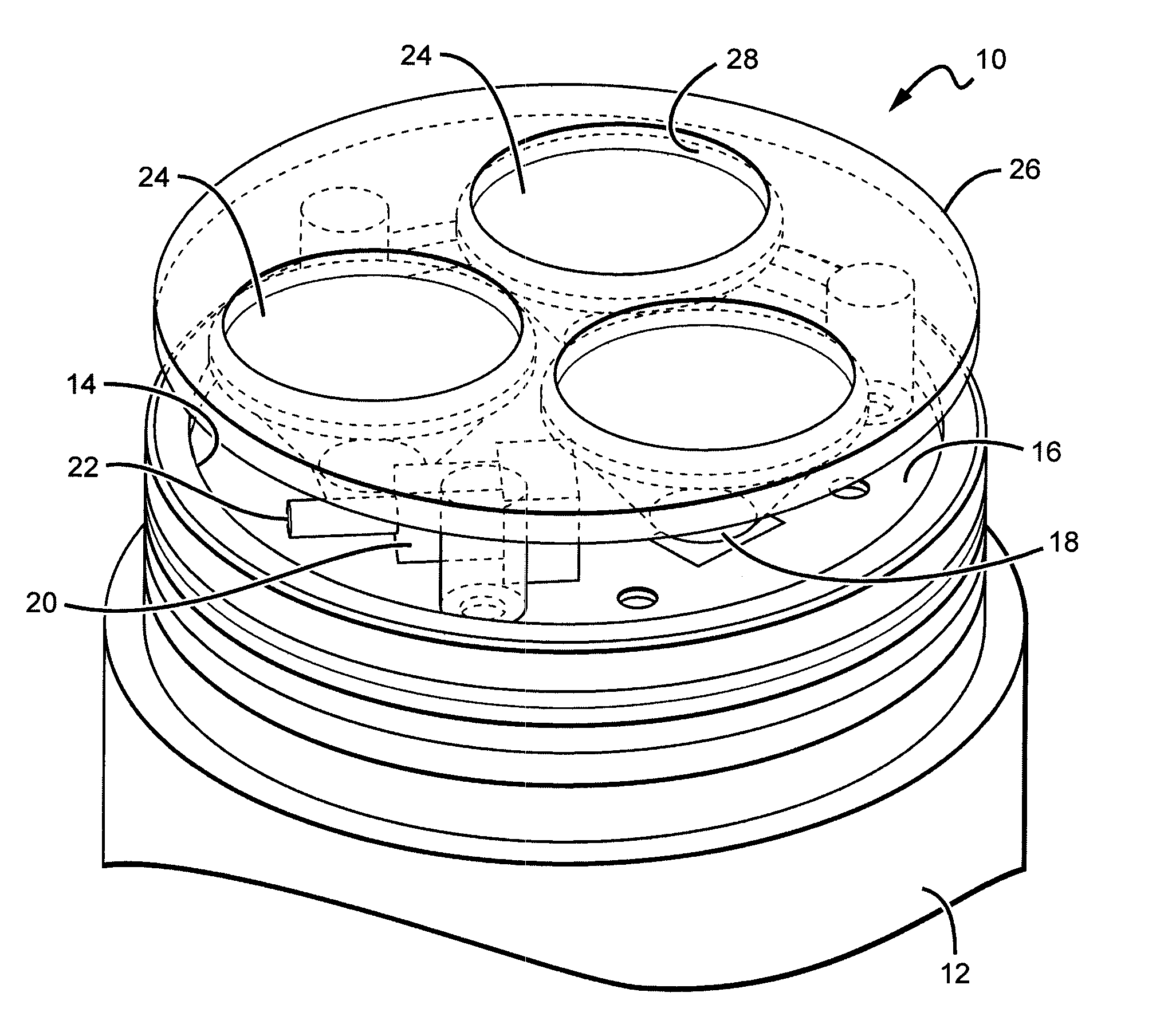
[0025]The present invention provides solid state lighting fixtures each of which has its own dimming control mechanism and circuitry. This allows for an enhanced level of lighting control in landscape lighting systems utilizing lighting fixtures according to the present invention. The present invention is particularly applicable to low voltage architectural and landscape lighting systems where it can be difficult to arrange a dimming circuit, though the invention would also be applicable to lighting systems that operate at line voltage. The output of each of the fixtures can be controlled to allow for tailoring output of the system to match its particular use.

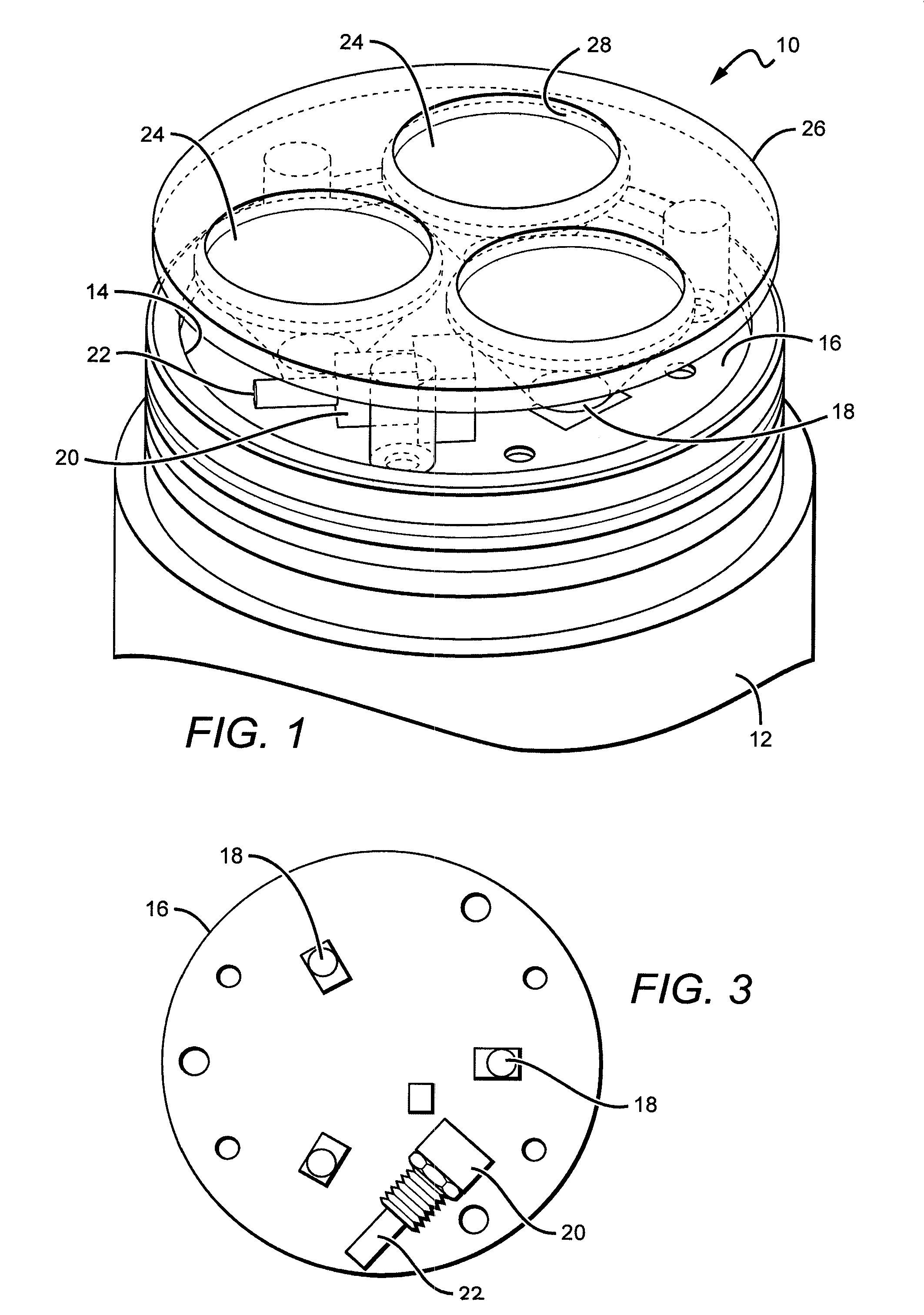
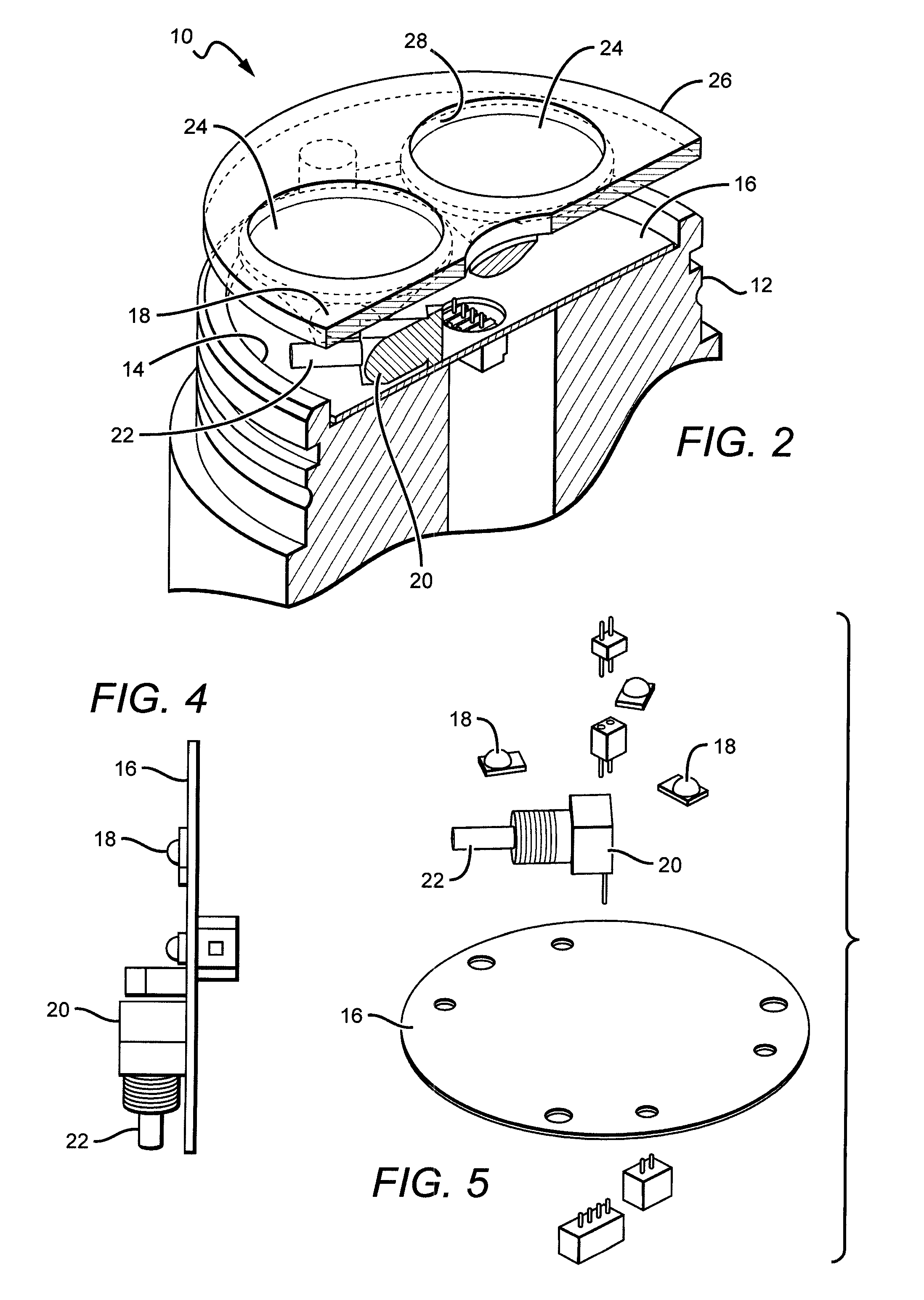
[0026]In some embodiments the dimming control device can be included on a printed circuit board (PCB) that also has the solid state light source, with the PCB having conductive traces to interconnect the dimming device, light sources, and other fixture components. Many different dimming devices can be used according to the pres...


PUM


Abstract

Improved lighting fixtures are described each of which having its own dimming or intensity control capability that allows for providing the desired lighting output or luminous flux, at each of the fixtures. This capability can be embodied in a dimming device at each fixture that can be manually or wirelessly operated. The present invention is particularly applicable to low voltage landscape or architectural lighting systems, and allows for customizing of the system to meet the particular application. The present invention also allows for tuning of the output for each fixture to compensate for variations in emission.

Description

[0001]This application claims the benefit of U.S. Provisional Patent Application Ser. No. 61 / 470,398, filed on Mar. 31, 2011.BACKGROUND OF THE INVENTION[0002]1. Field of the Invention[0003]This invention relates to solid state light fixtures, some of which utilize light emitting diodes or light emitting diode packages as their light source.[0004]2. Description of the Related Art[0005]Light emitting diodes (LED or LEDs) are solid state devices that convert electric energy to light, and generally comprise one or more active layers of semiconductor material sandwiched between oppositely doped layers. When a bias is applied across the doped layers, holes and electrons are injected into the active layer where they recombine to generate light. Light is emitted from the active layer and from all surfaces of the LED.[0006]Technological advances over the last decade or more have resulted in LEDs having a smaller footprint, greater luminous flux, increased emitting efficiency, and reduced cos...

Claims


Application Information

Patent Timeline
IPC IPC(8): H05B37/02
CPCH05B33/0815H05B37/02F21V17/002F21V23/005F21Y2113/005F21V23/0435F21W2131/107F21W2131/109F21Y2101/02F21V23/04F21Y2115/10F21Y2113/13H05B47/19H05B45/10H05B47/10
Inventor HAGEN, DOUGLAS W.
Owner B K LIGHTING
Why Eureka
Try Eureka