Automotive Radar Transmitter Architecture

Active Publication Date: 2013-04-11
INFINEON TECH AG
View PDF13 Cites 24 Cited by
  • Summary
  • Abstract
  • Description
  • Claims
  • Application Information

AI Technical Summary

Problems solved by technology

The frequencies that most radar systems operate at are sufficiently high (e.g., 24 GHz) such that the radar front

Method used


Image

  • Automotive Radar Transmitter Architecture
  • Automotive Radar Transmitter Architecture
  • Automotive Radar Transmitter Architecture

Examples


Embodiment Construction

[0011]The present invention will now be described with reference to the attached drawing figures, wherein like reference numerals are used to refer to like elements throughout, and wherein the illustrated structures and devices are not necessarily drawn to scale.

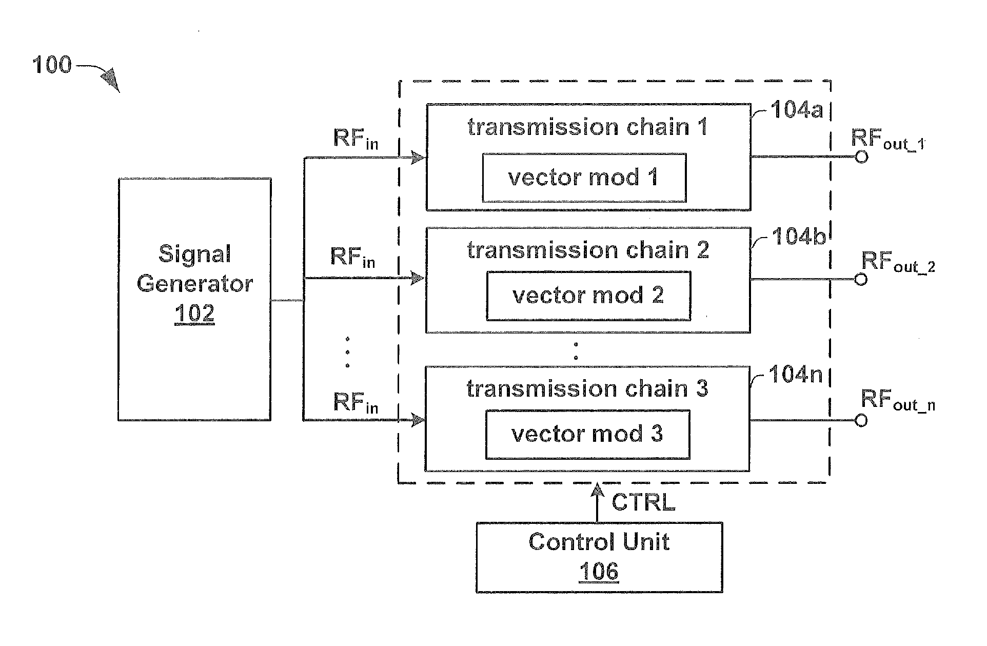
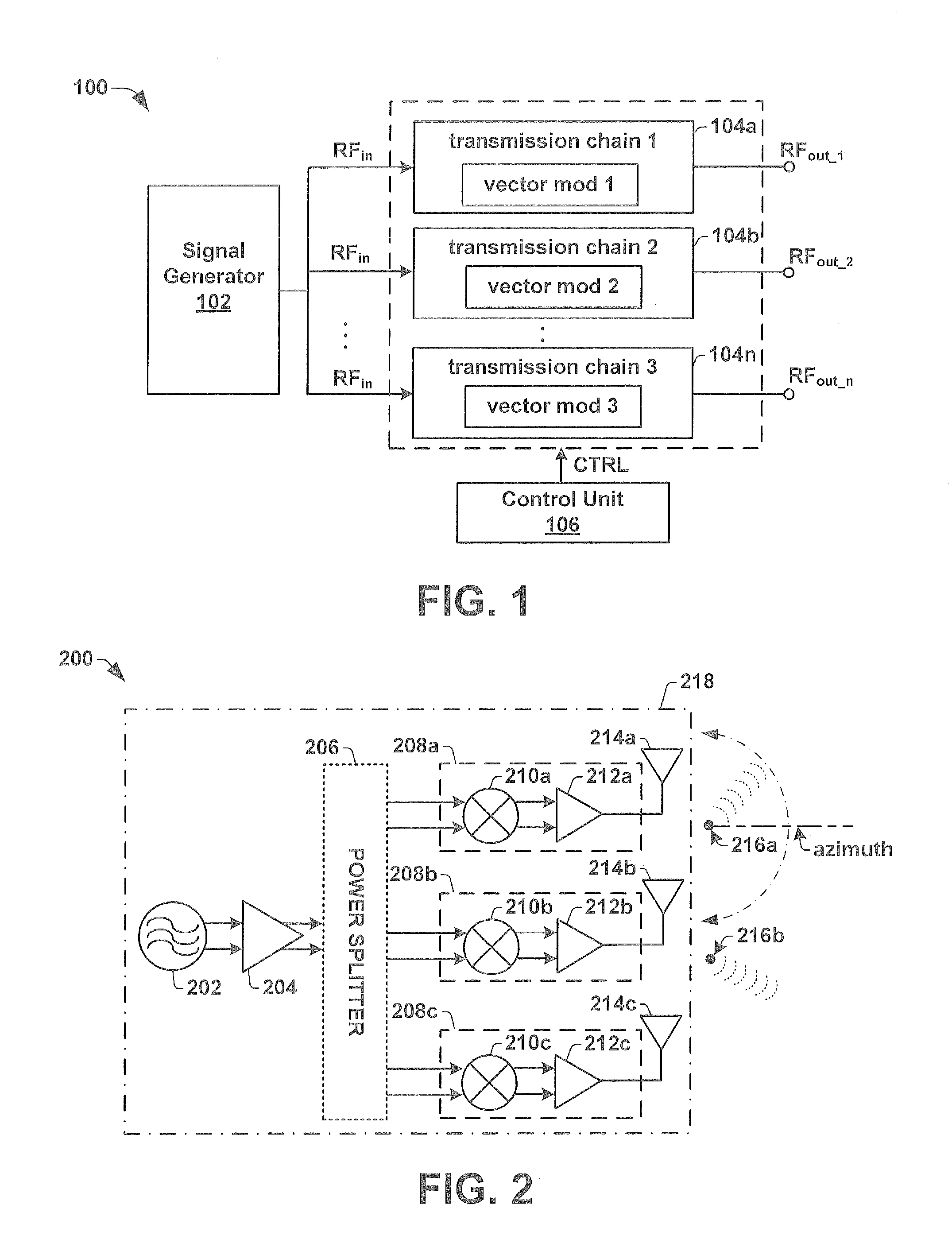
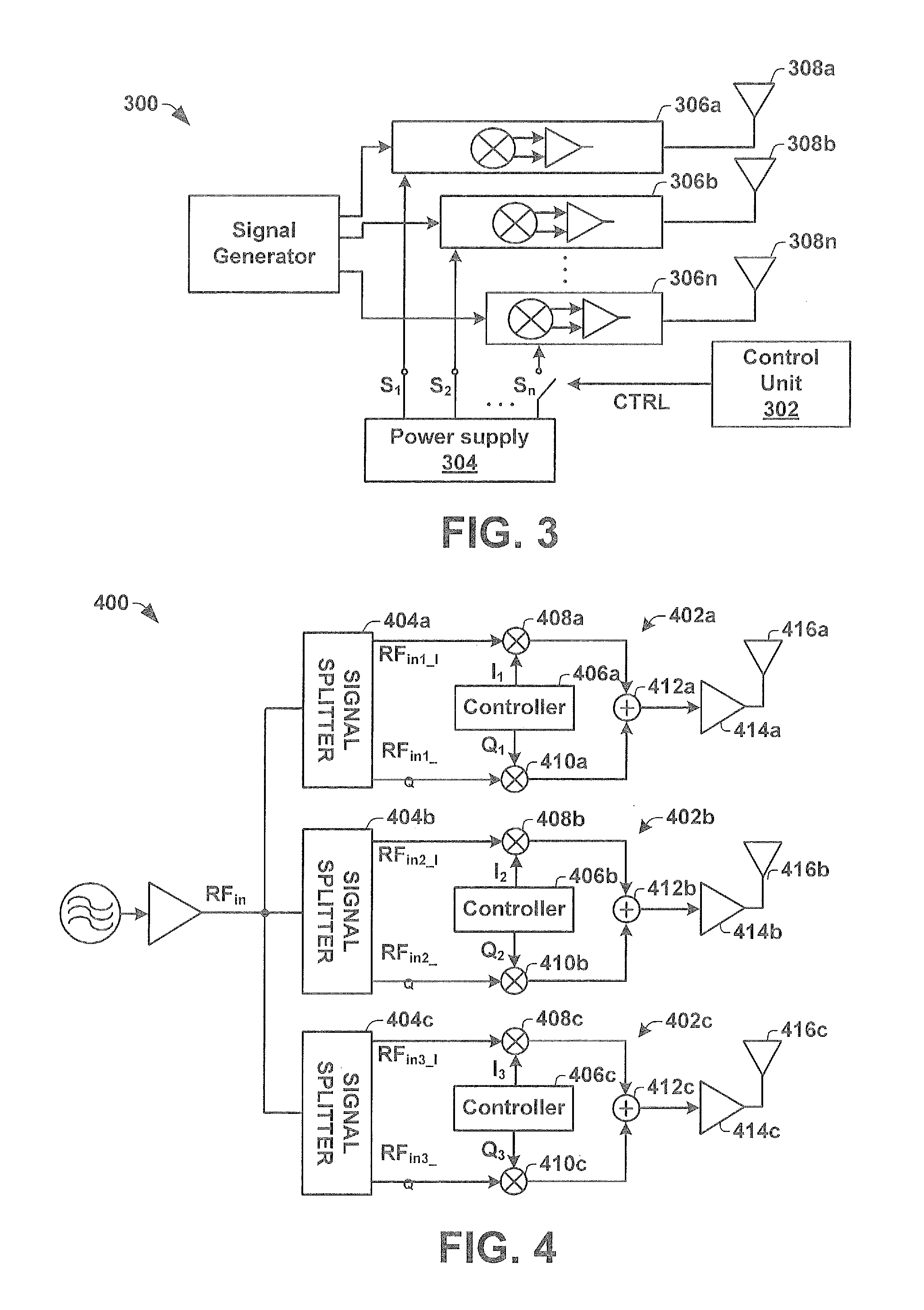
[0012]Some aspects of the present disclosure provide for a digital beam forming (DBF) radar transmitter comprised within a single integrated chip substrate, which is capable of continuous beam steering of a transmitted radar beam as well as changing the physical position of the origin of the transmitted radar beam. The DBF radar transmitter comprises a signal generator configured to generate a high frequency (e.g., radio frequency) input signal. The high frequency input signal is provided as an input to a plurality of independent transmission chains, which contain independently operated vector modulators (e.g., having IQ mixers) that are configured to introduce an individual phase adjustment to the high frequency input signa...


PUM


Abstract

One embodiment of the present invention relates to a radar transmitter comprised within a single integrated chip substrate, which is capable of continuous beam steering of a transmitted radar beam as well as an option to change the physical position of the origin of the transmit radar beam. The radar transmitter has a signal generator that generates an RF signal. The RF signal is provided to a plurality of independent transmission chains, which contain independently operated vector modulators configured to introduce an individual phase adjustment to the high frequency input signal to generate separate RF output signals. A control unit is configured to selectively activate a subset of (e.g., two or more) the independent transmission chains. By activating the subset of independent transmission chains to generate RF output signals with separate phases, a beam steering functionality is enabled. Furthermore, the subset defines a changeable position of the transmitted radar beam.

Description

BACKGROUND OF THE INVENTION[0001]Radar systems are becoming increasingly common in modern motor vehicles. Radar systems can detect the location of objects around a vehicle and allow the vehicle to respond accordingly. For example, autonomous cruise control (ACC) systems utilize a radar system to detect the location and / or velocity of objects around an automobile. The radar system provides signals corresponding to the detected location and / or velocity to a digital signal processor (DSP), which in response to the signals, automatically adjusts the automobile's speed in order to maintain a safe distance (e.g., if an object is detected in front of the automobile, the DSP sends a signal to the engine or braking system to decelerate).[0002]Radar systems often operate according to a phase monopulse azimuth detection method, which allows for detection of an object's angle and distance relative to a vehicle. The phase monopulse azimuth detection method utilizes two or more receiving antennas...

Claims


Application Information

Patent Timeline
IPC IPC(8): G01S13/00H01Q3/00G01S13/931
CPCH01Q1/3233G01S7/032G01S13/584G01S13/931G01S2013/0245G01S2013/9321H01Q3/26H01Q3/24H01Q21/06H04B7/0617G01S2007/358G01S7/358G01S7/02
Inventor FORSTNER, JOHANN PETERGERLACH, UDO
Owner INFINEON TECH AG
Why Eureka
Try Eureka