Dual inner diameter ferrule device with smooth internal contours and method

a technology of inner diameter and internal contour, applied in the direction of lamination ancillary operations, instruments, chemistry apparatus and processes, etc., can solve the problems of fiber breakage at the rear interface area and tend to increase the breakag

a technology of inner diameter and internal contour, applied in the direction of lamination ancillary operations, instruments, chemistry apparatus and processes, etc., can solve the problems of fiber breakage at the rear interface area and tend to increase the breakag

US20130089294A1Active Publication Date: 2013-04-11COMMSCOPE TECH LLC

Image

  • Dual inner diameter ferrule device with smooth internal contours and method
  • Dual inner diameter ferrule device with smooth internal contours and method
  • Dual inner diameter ferrule device with smooth internal contours and method

Examples


Embodiment Construction

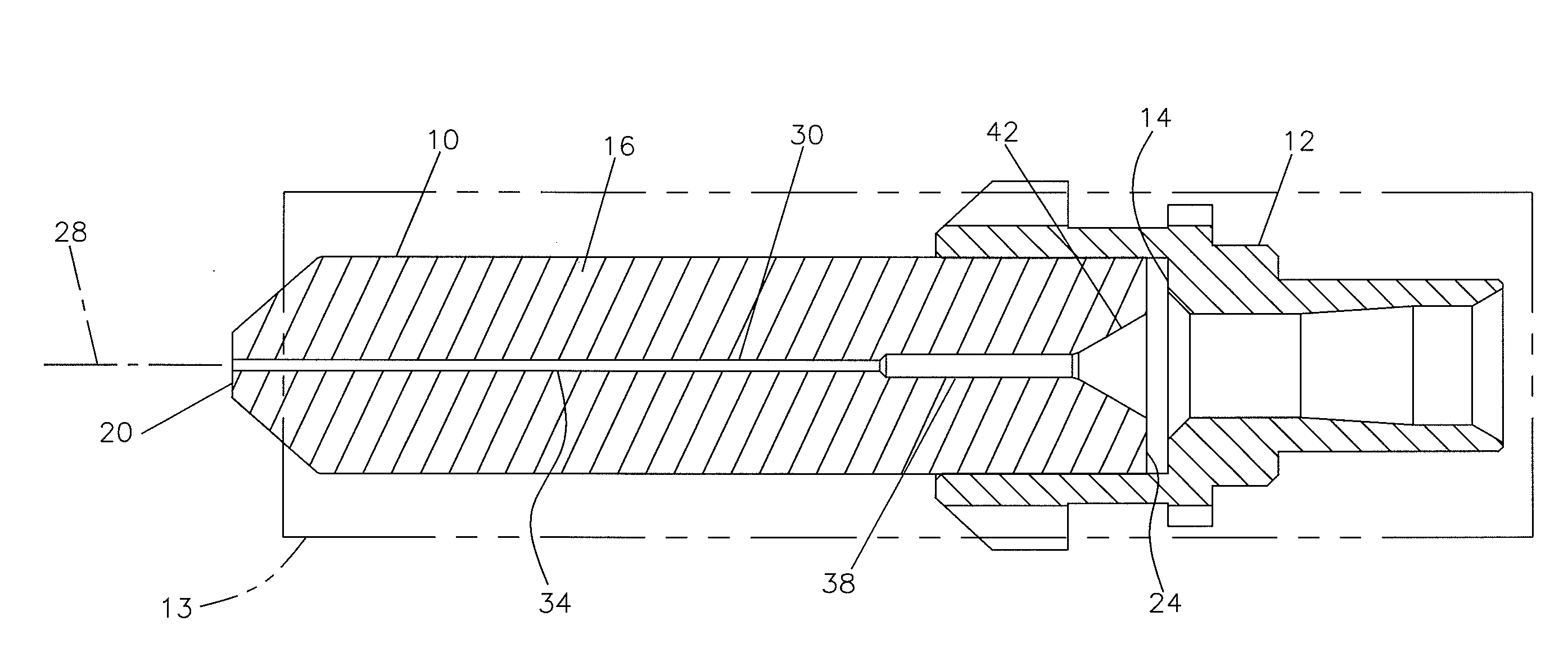
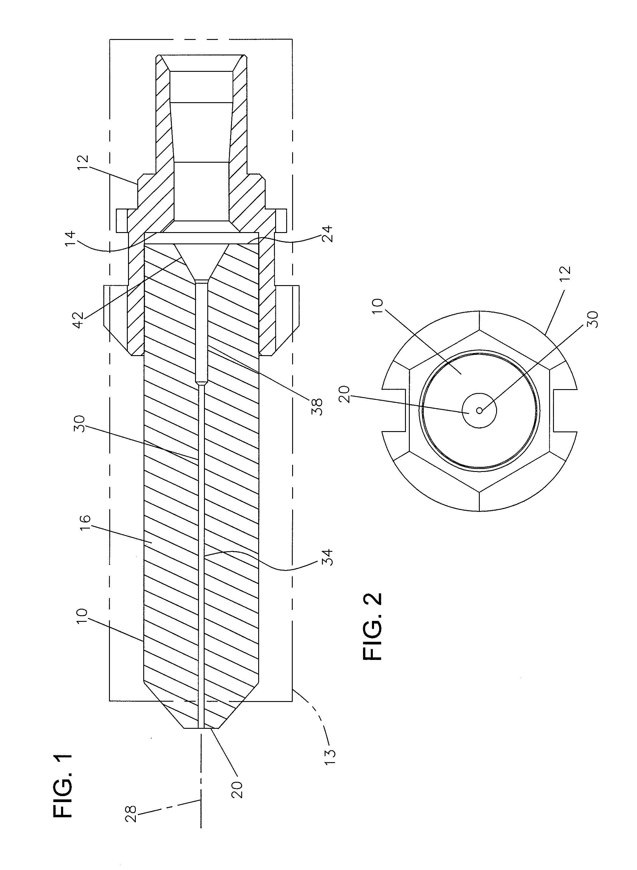
[0029]Referring now to FIGS. 1-7, a preferred embodiment of a fiber optic ferrule 10 is shown mounted to a hub 12. Generally, ferrule 10 and hub 12 are secured together by convenient methods including press fit or adhesive mounts. Ferrule 10 and hub 12 are mounted within a connector housing 13 shown in dashed lines in FIG. 1. Connector housing 13 can be one of a variety of well known connector types, including SC, FC, ST, LX.5, LC, and others. As will be described below, ferrule 10 and hub 12 are connected to an end of a fiber optic cable for use in connectorizing the end of the cable.

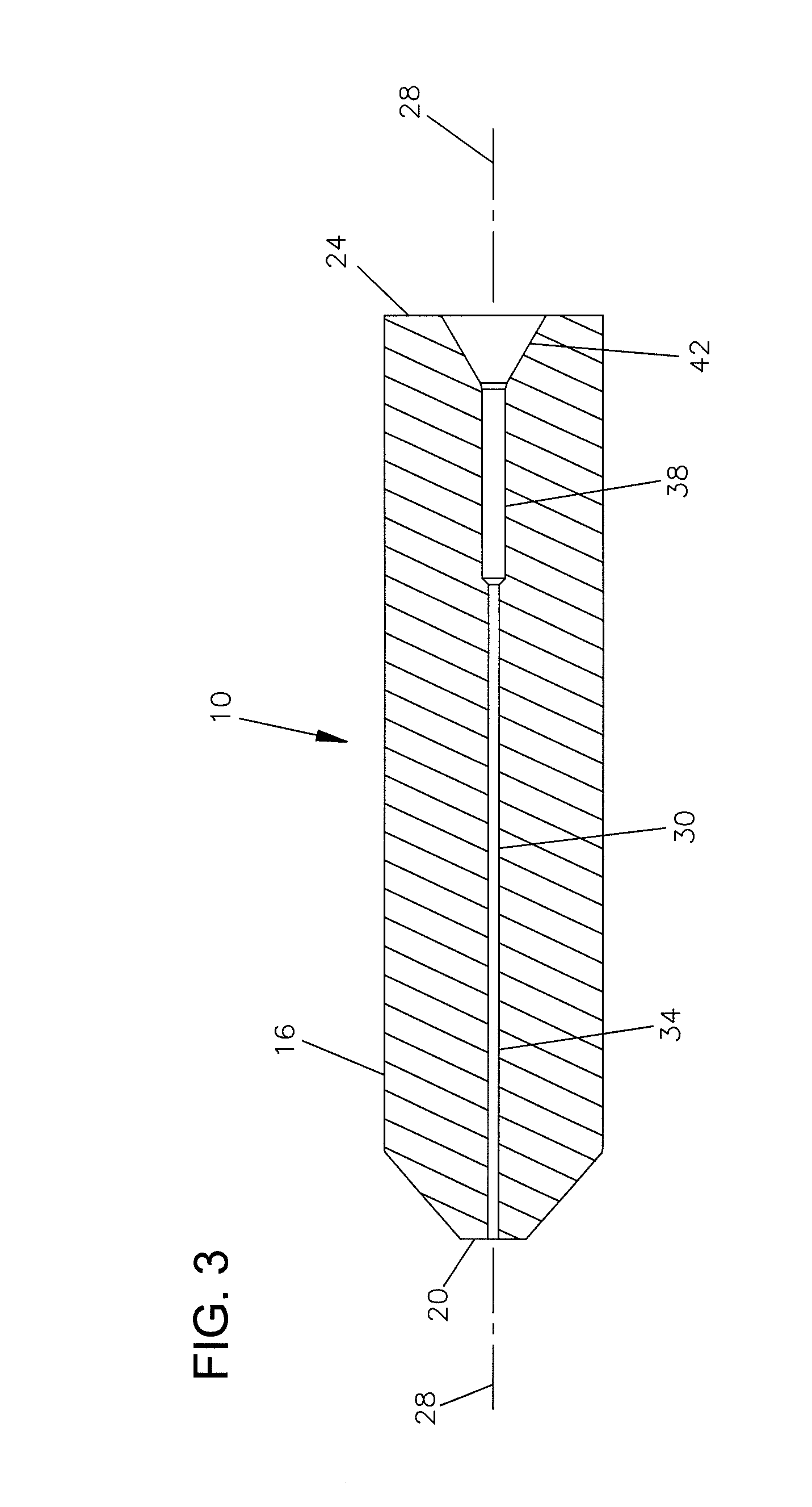
[0030]Ferrule 10 includes a body 16 with a first end 20 defining a ferrule tip. Body 16 of ferrule 10 includes an opposite end 24 received in a pocket 14 of hub 12. Ferrule 10 includes a central axis 28. First end 20 of ferrule 10 is typically polished along with the fiber after the fiber is installed. Body 16 of ferrule 10 is typically ceramic in construction.

[0031]Ferrule 10 includes a central passag...


PUM

PropertyMeasurementUnit
Diameteraaaaaaaaaa
Diameteraaaaaaaaaa
Diameteraaaaaaaaaa

Abstract

A fiber optic ferrule includes a body extending from a first end to a second opposite end, with the body including an axial passage extending between the first and the second ends. The axial passage includes a first diameter portion having a diameter of at least 125 microns, a second diameter portion having a diameter of at least 250 microns and less than a diameter of a buffer, and a smooth and continuous transition between the first and the second diameter portions. The second diameter portion is positioned between the first diameter portion and the second end. The axial passage further defines a tapered shape at the second end extending inward from the second end toward the second diameter portion. In certain embodiments, another smooth and continuous transition can be provided between the taper shape and the second diameter portion. In certain embodiments, the axial passage is smooth and continuous between the first and the second ends of the body. A hub holds the ferrule. A method of assembling a terminated fiber optic cable is also provided.

Description

CROSS REFERENCE TO RELATED APPLICATIONS[0001]The present application claims the benefit of U.S. Provisional Patent Application Ser. No. 61 / 545,444, filed Oct. 10, 2011, entitled DUAL INNER DIAMETER FERRULE DEVICE WITH SMOOTH INTERNAL CONTOURS AND METHOD, which application is hereby incorporated by reference in its entirety. This application is related to application Ser. No. 13 / 114,721, filed May 24, 2011, which is a continuation of application Ser. No. 12 / 271,335, filed Nov. 14, 2008, now abandoned, which is a continuation of application Ser. No. 11 / 972,373, filed Jan. 10, 2008, now U.S. Pat. No. 7,452,137, which is a continuation of application Ser. No. 11 / 497,175, filed Aug. 1, 2006, now U.S. Pat. No. 7,341,383, which applications are incorporated herein by reference in their entirety.FIELD OF THE INVENTION[0002]The present disclosure relates to terminating the ends of fiber optic cables with ferrules.BACKGROUND OF THE INVENTION[0003]Typically the end of a fiber optic cable is te...

Claims


Application Information

Patent Timeline
11 Apr 2013
Publication
US20130089294A1
IPC
G02B6/36; B32B38/10
CPC
G02B6/3837; G02B6/3861; G02B6/3838; G02B6/3869; G02B6/3854; G02B6/3865
Inventors
ZIMMEL, STEVEN C.