

Bullets With Lateral Damage Stopping Power
- Summary
- Abstract
- Description
- Claims
- Application Information
AI Technical Summary
Benefits of technology
Problems solved by technology
Method used
Image

Examples
example 1
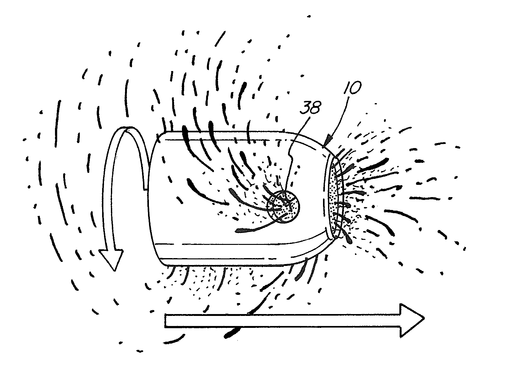
[0038]Winchester Silvertip® hollow point bullets in .32ACP caliber were used in comparative testing. Both modified and unmodified rounds were fired into Perma-Gel® ballistic gel using a Seecamp LWS .32 pistol.
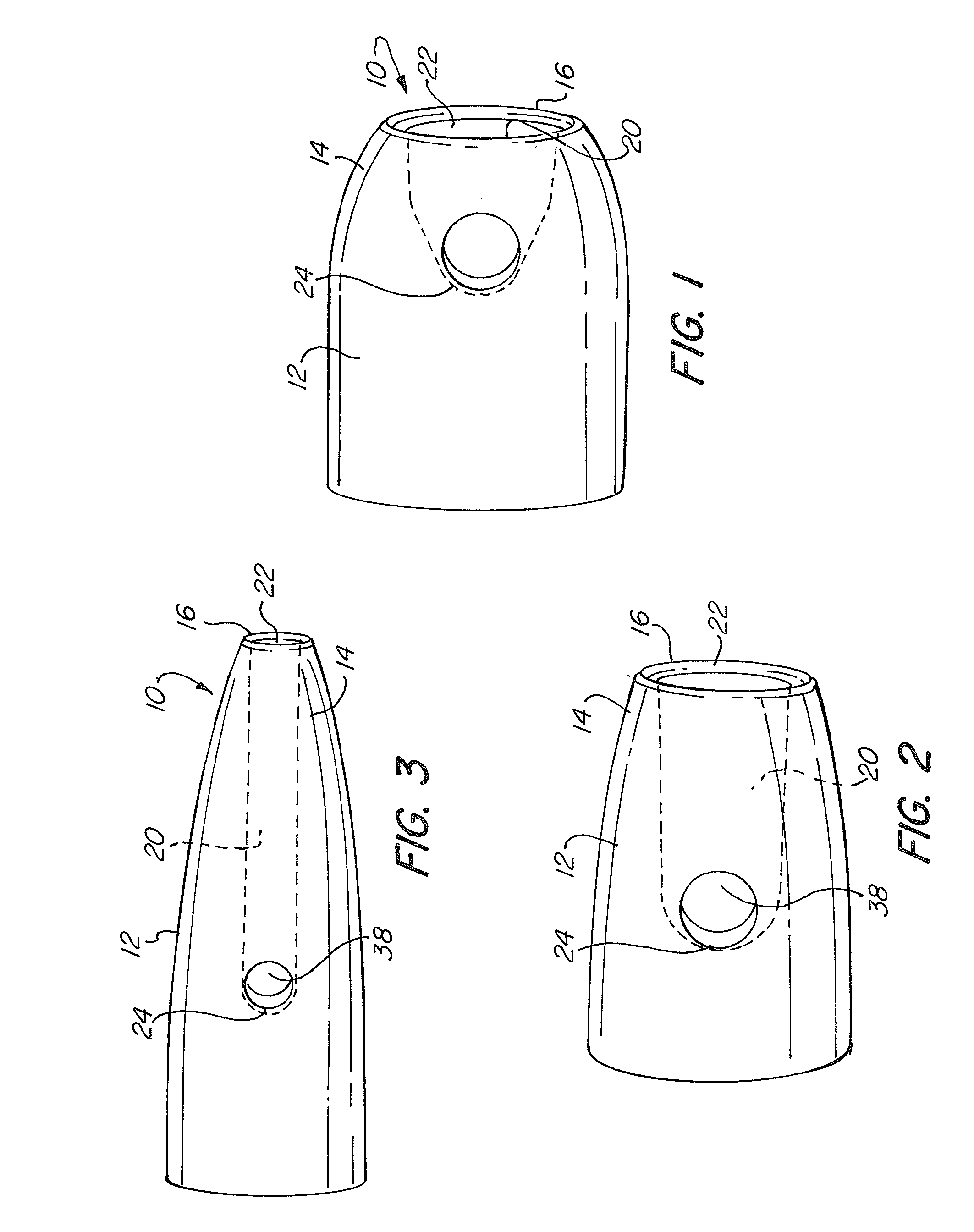
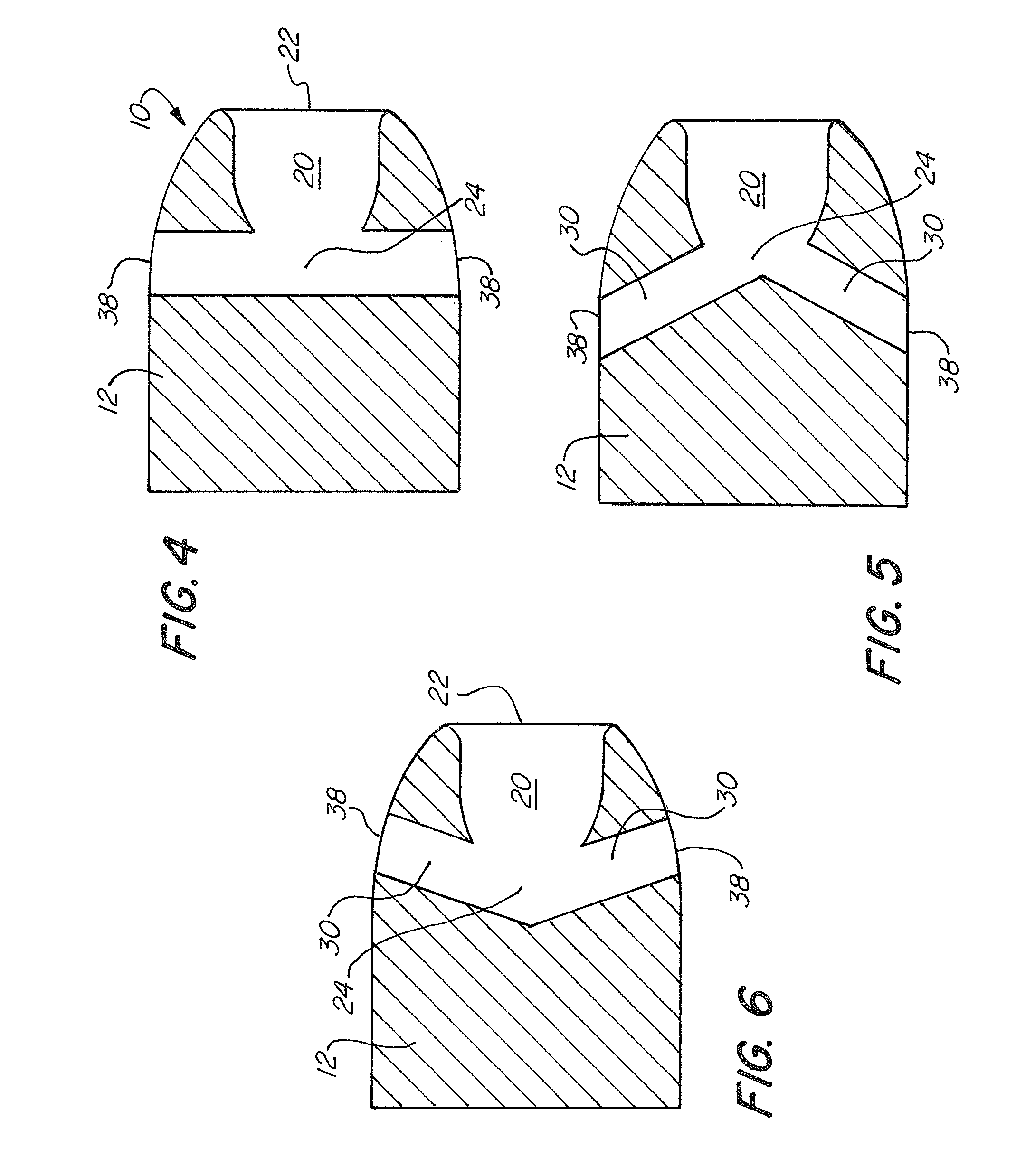
[0039]The modified bullets were made by drilling two bores, (also called side holes in these examples) of approximately 3 / 32 of an inch directly opposite each other at the bottom of the hollow point cup in the tip of the bullets. The side holes were plugged with a low melting fusible alloy. The particular alloy used has all the physical properties of lead but will melt in warm water. The cup of the modified bullet was filled with black pepper in contemplation of being able to see damage done to the translucent gel more easily.
[0040]Unmodified rounds from the same Winchester lot number and ammunition box were used as a control and comparison.
[0041]Upon firing at about a two foot distance, both the modified and unmodified Winchester Silvertip rounds went through 12 inches of gela...
example 2
[0044]In a second test, the modified Silvertip round having two side holes of approximately 3 / 32 of an inch directly opposite each other at the bottom of the hollow point cup in the tip of the bullets was used; neither side hole was plugged and the bullet was not filled with pepper. An unmodified control round from the same lot number was also tested. Both the modified and unmodified rounds were fired into Perma-Gel ballistic gel as before.
[0045]The unmodified round passed through twelve inches of gelatin and buried itself in a phone book behind the gel. Some paper tearing was visible at over 200 pages into the book. The recovered bullet showed no deformation of the unmodified bullet. The path of the unmodified bullet appeared as a straight line with little or no gel deformation beyond the path of the bullet.
[0046]The modified round passed through twelve inches of gelatin and bounced off the cover of the phone book and left a very slight marking on the first few pages of the book. T...
example 3
[0047]Winchester Silvertip® bullets in .32ACP caliber were modified so that two side holes of approximately 3 / 32 of an inch were situated directly opposite each other at the bottom of the cup. Some modified bullets were additionally modified by filling the cup with pepper and by fitting a thin copper jacket over the cup to retain the pepper. Unmodified rounds from the same Winchester lot number and ammunition box were again used as a control. The pistol used was again a Seecamp LWS .32. The three different rounds were discharged into phone books at a 6 foot range.
[0048]The unmodified Winchester Silvertip had the greatest penetration. It left an impression into about 1.9 inches of phone book paper. The cup of the unmodified round just filled up with paper and thereafter apparently performed just like regular ball ammo would. No deformation of the bullet was observed.
[0049]The modified Winchester Silvertip with the modified two side hole bullet left an impression on approximately 1.4 ...
PUM
 Abstract
Description
Claims
Application Information