Camera washing device for camera lens

a technology for washing devices and cameras, applied in vehicle cleaning, vehicle maintenance, spray nozzles, etc., can solve the problem that the driver of a motor vehicle cannot see the image detected, and achieve the effect of reducing the time required to inject water particles and reducing the entire water consumption

Active Publication Date: 2013-04-18
DENSO CORP
View PDF6 Cites 162 Cited by
  • Summary
  • Abstract
  • Description
  • Claims
  • Application Information

AI Technical Summary

Benefits of technology

[0011]In the structure of the camera washing device according to the exemplary embodiment of the present invention, the high pressure air flowing in the high pressure air passage and the wash water supplied to the wash water passage in the junction joint are mixed together in order to generate water particles as the mixture of the high-pressure air a...

Problems solved by technology

However, because the structure of the conventional camera washing device consumes a lot of wash water in order to spray wash water on the surface of the front glass of the in-vehicle camera, it is necessary to frequently supply wash water into a water tank.
Because the conventi...

Method used


Image

  • Camera washing device for camera lens
  • Camera washing device for camera lens
  • Camera washing device for camera lens

Examples


first exemplary embodiment

[0036]A description will be given of the camera washing device for an in-vehicle camera according to a first exemplary embodiment of the present invention.

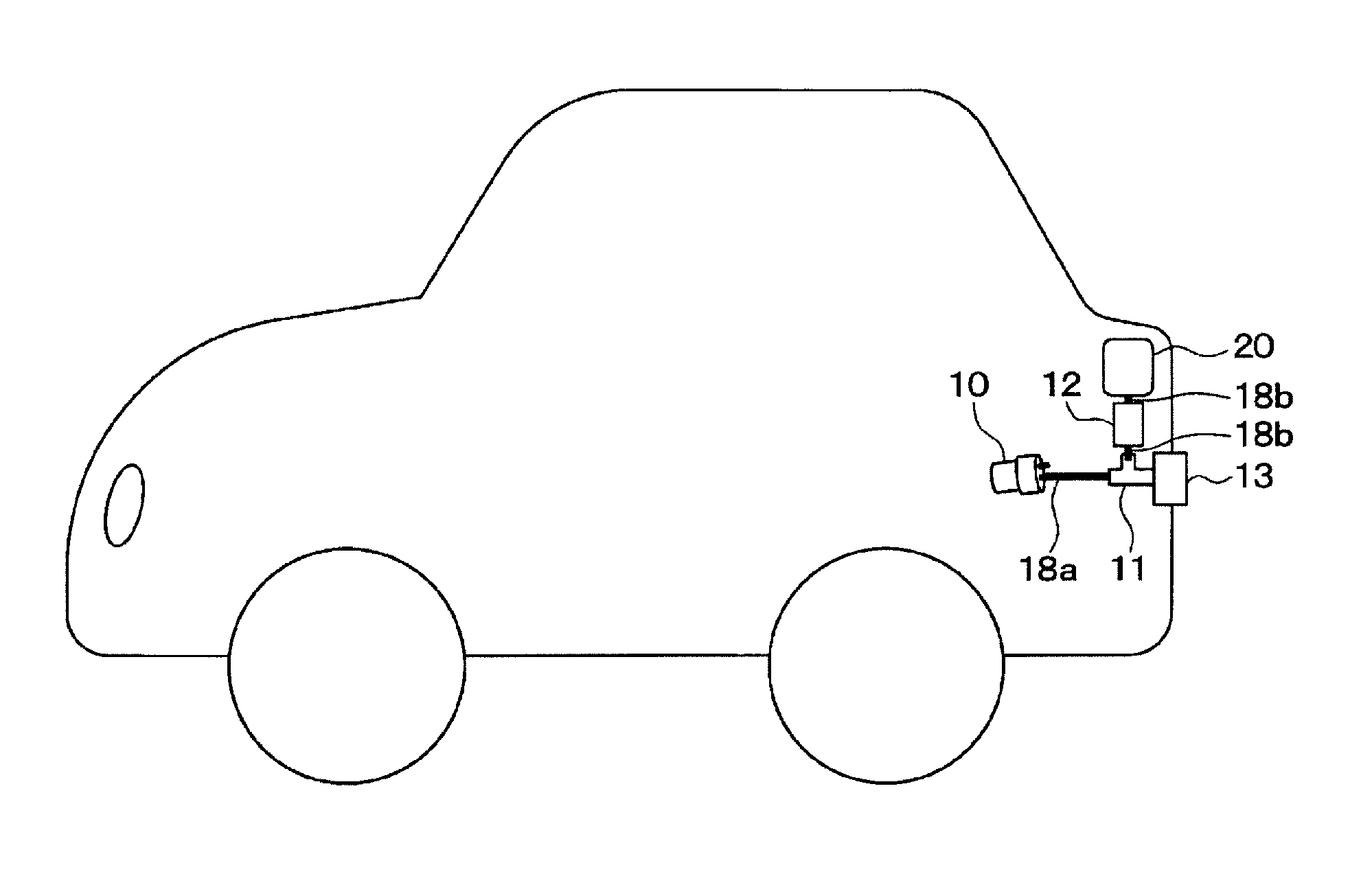
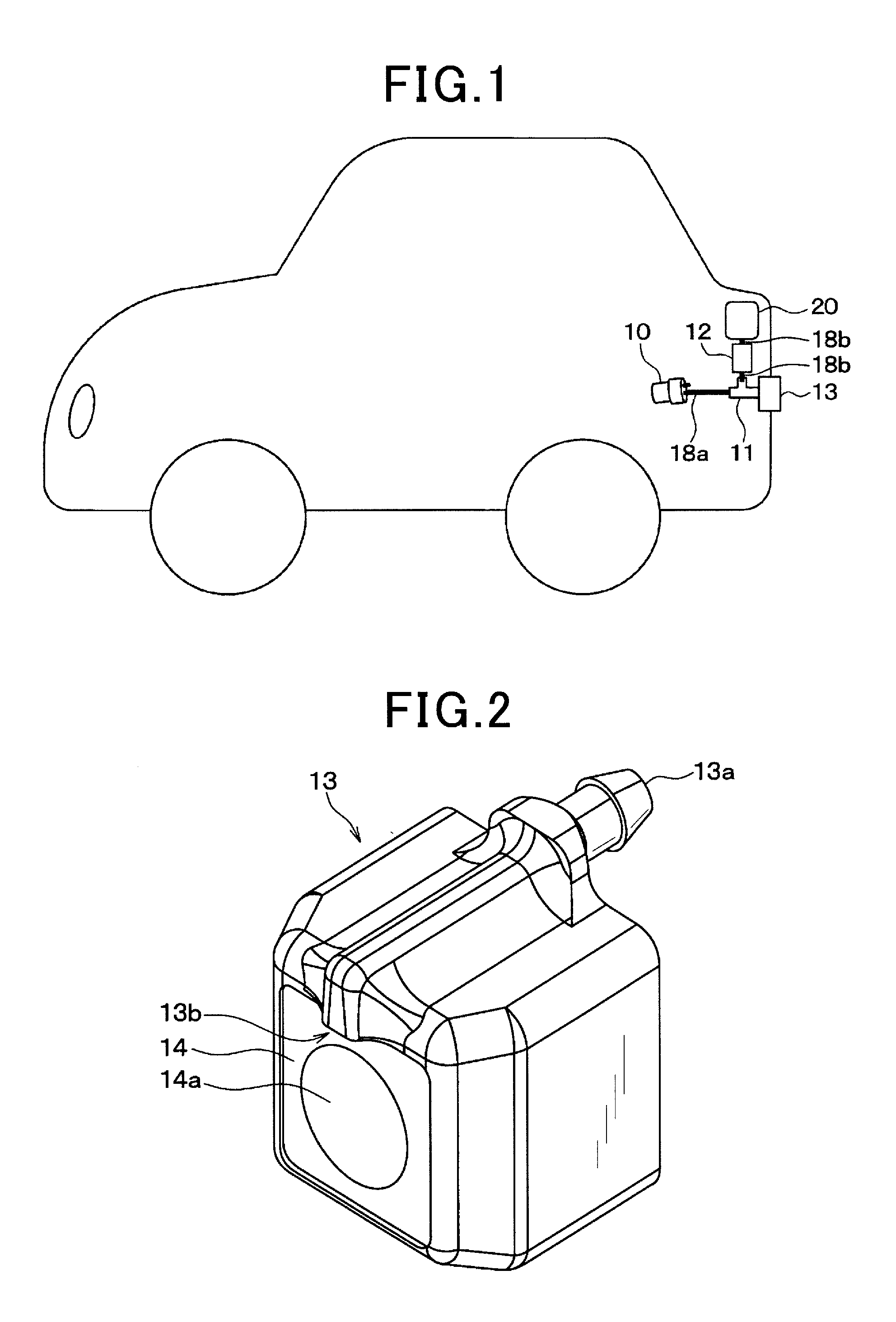
[0037]FIG. 1 is a schematic view showing an entire structure of the camera washing device for the in-vehicle camera according to the first exemplary embodiment of the present invention.

[0038]As shown in FIG. 1, the camera washing device according to the first exemplary embodiment has an air pump 10, a junction joint 11, an electromagnetic valve 12 (as the open-close part used in the claims), an injection nozzle 13, and a high-pressure air pipe 18a and a wash water pipe 18b, etc.

[0039]The injection nozzle 13 is equipped with a built-in rear camera 14. The rear camera 14 will be described later in detail with reference to FIG. 2.

[0040]The electromagnetic valve 12 is connected to a wash water tank 20. The wash water tank 20 stores wash water such as water only, rinse water or a water-detergent mixture.

[0041]For example, the camera wa...

second embodiment

[0102]Next, a description will be given of the camera washing device according to the second exemplary embodiment of the present invention with reference to FIG. 11 and FIG. 12.

[0103]FIG. 11 is a schematic view showing an entire structure of the camera washing device for an in-vehicle camera according to the second exemplary embodiment of the present invention.

[0104]The same components between the first exemplary embodiment shown in FIG. 1 and the second exemplary embodiment shown in FIG. 11 will be referred with the same reference numbers and characters. The explanation of the same components is omitted here for brevity.

[0105]As previously described, the camera washing device according to the first exemplary embodiment has the structure in which the wash water tank 20 is arranged at a position which is higher than the position of the electromagnetic valve 12. In this structure, the wash water stored in the tank flows into the high-pressure air passage 11a through the wash water pip...

third embodiment

[0111]Next, a description will be given of the camera washing device according to the third exemplary embodiment of the present invention with reference to FIG. 13 and FIG. 14.

[0112]FIG. 13 is a schematic view showing an entire structure of the camera washing device for an in-vehicle camera according to the third exemplary embodiment of the present invention;

[0113]The same components between the first exemplary embodiment shown in FIG. 1 and the third exemplary embodiment shown in FIG. 13 will be referred with the same reference numbers and characters. The explanation of the same components is omitted here for brevity.

[0114]As previously described, the camera washing device according to the first exemplary embodiment has the structure shown in FIG. 1 in which the wash water tank 20 is arranged at a position which is higher than the position of the electromagnetic valve 12 and the wash water stored in the wash water tank 20 flows into the high-pressure air passage 11a through the was...


PUM


Abstract

A camera washing device has an air pump, a wash water tank storing wash water, an injection nozzle with an injection part, a junction joint having a high-pressure air passage and a wash water passage, and an electromagnetic valve. The air pump generates and supplies high-pressure air to the high-pressure air passage. When the control part instructs the electromagnetic valve to be switched to an open state, the wash water and the high-pressure air are mixed in the junction joint to generate water particles. The generated water particles are supplied to the injection nozzle. When the electromagnetic valve is switched to the open state after injecting the high-pressure air only to a lens of a rear camera, the injection part injects the water particles to the lens of the camera.

Description

CROSS-REFERENCE TO RELATED APPLICATION[0001]This application is related to and claims priority from Japanese Patent Applications No. 2011-226899 filed on Oct. 14, 2011, and No. 2012-150266 filed on Jul. 4, 2012, the contents of which are hereby incorporated by reference.BACKGROUND OF THE INVENTION[0002]1. Field of the Invention[0003]The present invention relates to camera washing devices capable of washing and cleaning a camera lens, for example, of an in-vehicle rear camera, etc.[0004]2. Description of the Related Art[0005]There are various types of camera washing devices. For example, a conventional patent document, Japanese patent laid open publication No. JP 2001-171491 discloses a conventional camera washing device which washes a front glass or lens of an in-vehicle camera mounted on a motor vehicle. The conventional camera washing device is equipped with a high pressure air generation part. The high pressure air generation part generates high-pressure air. The conventional cam...

Claims


Application Information

Patent Timeline
IPC IPC(8): B05B1/10
CPCB60S1/485B60S1/486B60S1/56B60S1/54B60S1/52
Inventor TANAKA, HITOSHIMATSUMOTO, MUNEAKIMATSUKAWA, NORIFUMI
Owner DENSO CORP
Why Eureka
Try Eureka