Method for detecting metal foreign object in contactless power supply system, contactless power supply device, power reception device, and contactless power supply system

a technology of power supply system and metal foreign object, which is applied in the direction of electrochemical generators, instruments, transportation and packaging, etc., can solve the problems of inability to accurately detect metal foreign objects and high detection accuracy cannot be expected, so as to improve the detection accuracy and improve the detection accuracy

Active Publication Date: 2013-04-18
PANASONIC INTELLECTUAL PROPERTY MANAGEMENT CO LTD
View PDF3 Cites 47 Cited by
  • Summary
  • Abstract
  • Description
  • Claims
  • Application Information

AI Technical Summary

Benefits of technology

[0009]It is an object of the present invention to provide a method for detecting a metal foreign object with improved detection accuracy in a contactless power supply system.
[0010]The present invention provides a contactless power supply device, a power reception device, and a contactless power supply system that are suitable for implementing this metal foreign object that improves the metal foreign object detection accuracy.

Problems solved by technology

Thus, high detection accuracy cannot be expected.
Thus, the metal foreign object cannot be accurately detected.

Method used


Image

  • Method for detecting metal foreign object in contactless power supply system, contactless power supply device, power reception device, and contactless power supply system
  • Method for detecting metal foreign object in contactless power supply system, contactless power supply device, power reception device, and contactless power supply system
  • Method for detecting metal foreign object in contactless power supply system, contactless power supply device, power reception device, and contactless power supply system

Examples


first embodiment

[0054]A first embodiment of a contactless power supply system according to the present invention will now be described with reference to the drawings.

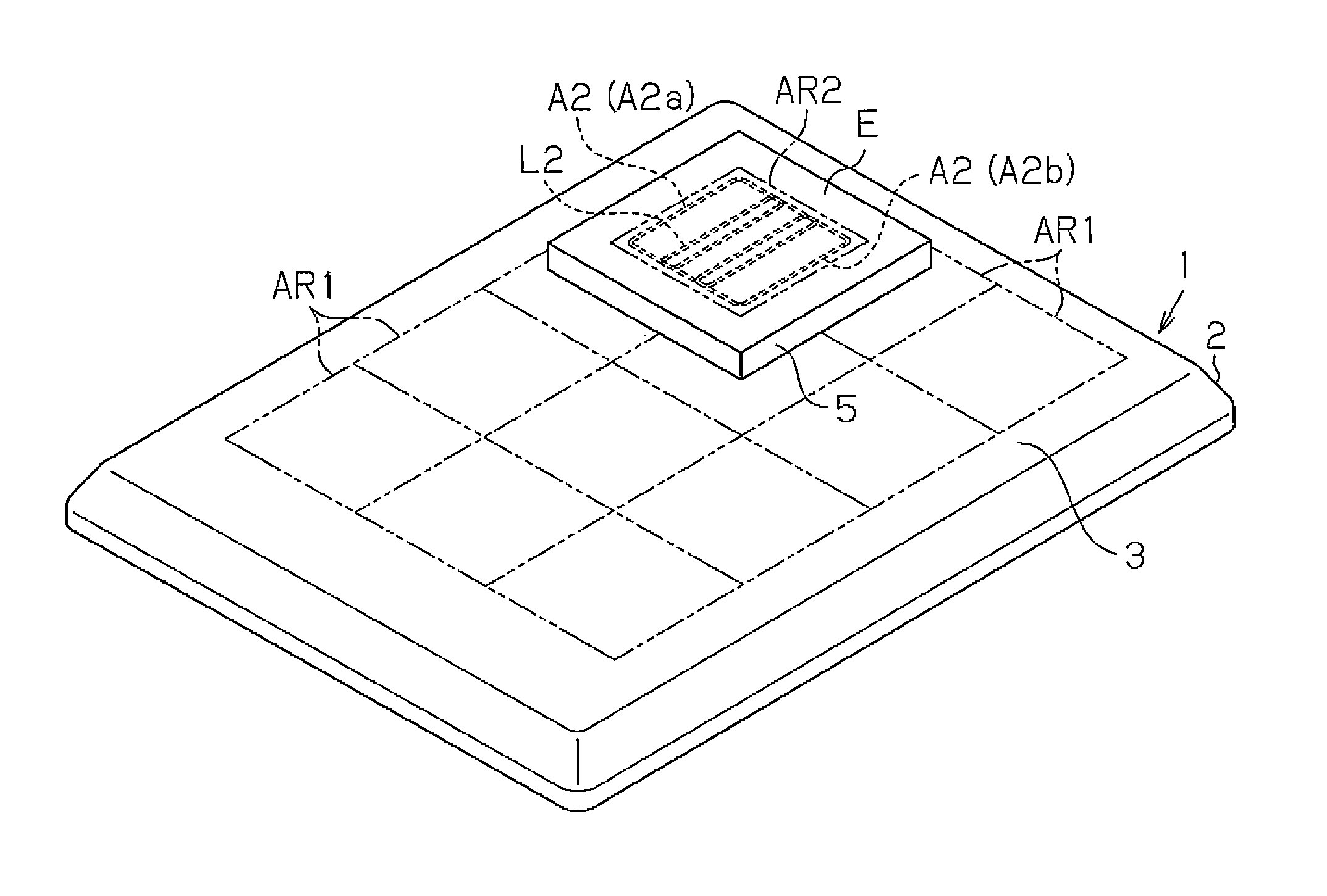
[0055]As illustrated in FIG. 1, the contactless power supply system includes a contactless power supply device (hereinafter simply referred to as the power supply device) 1 and an electric appliance E, which is supplied with power in a contactless manner from the power supply device 1.

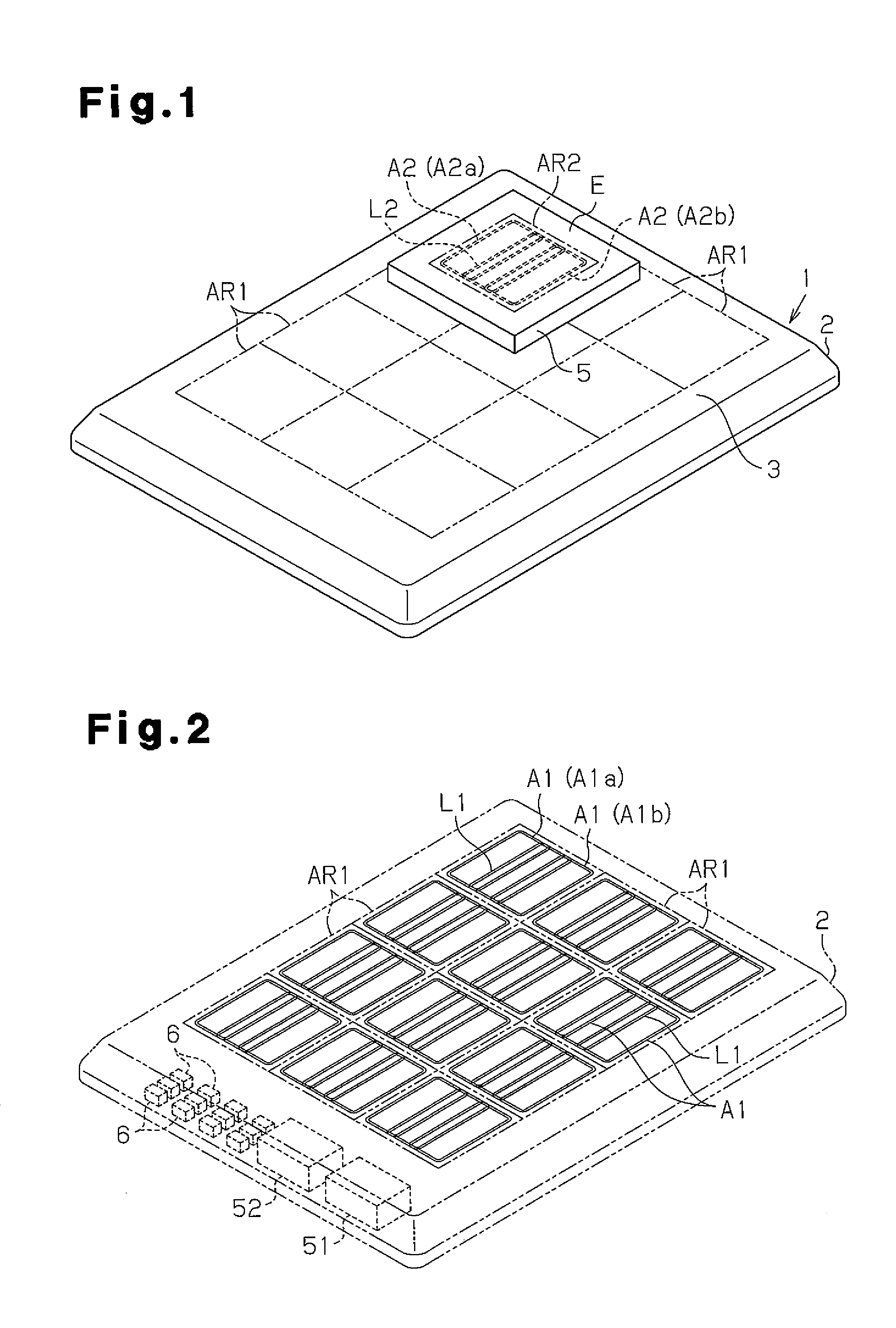
[0056]The power supply device 1 includes a tetragonal plate-shaped casing 2. The casing 2 includes a flat upper surface that forms a setting surface 3 on which the electric appliance E is set. A plurality of tetragonal power supply areas AR1 are formed on the setting surface 3. In the first embodiment, the power supply areas AR1 are arranged on the setting surface 3 in a three by four matrix.

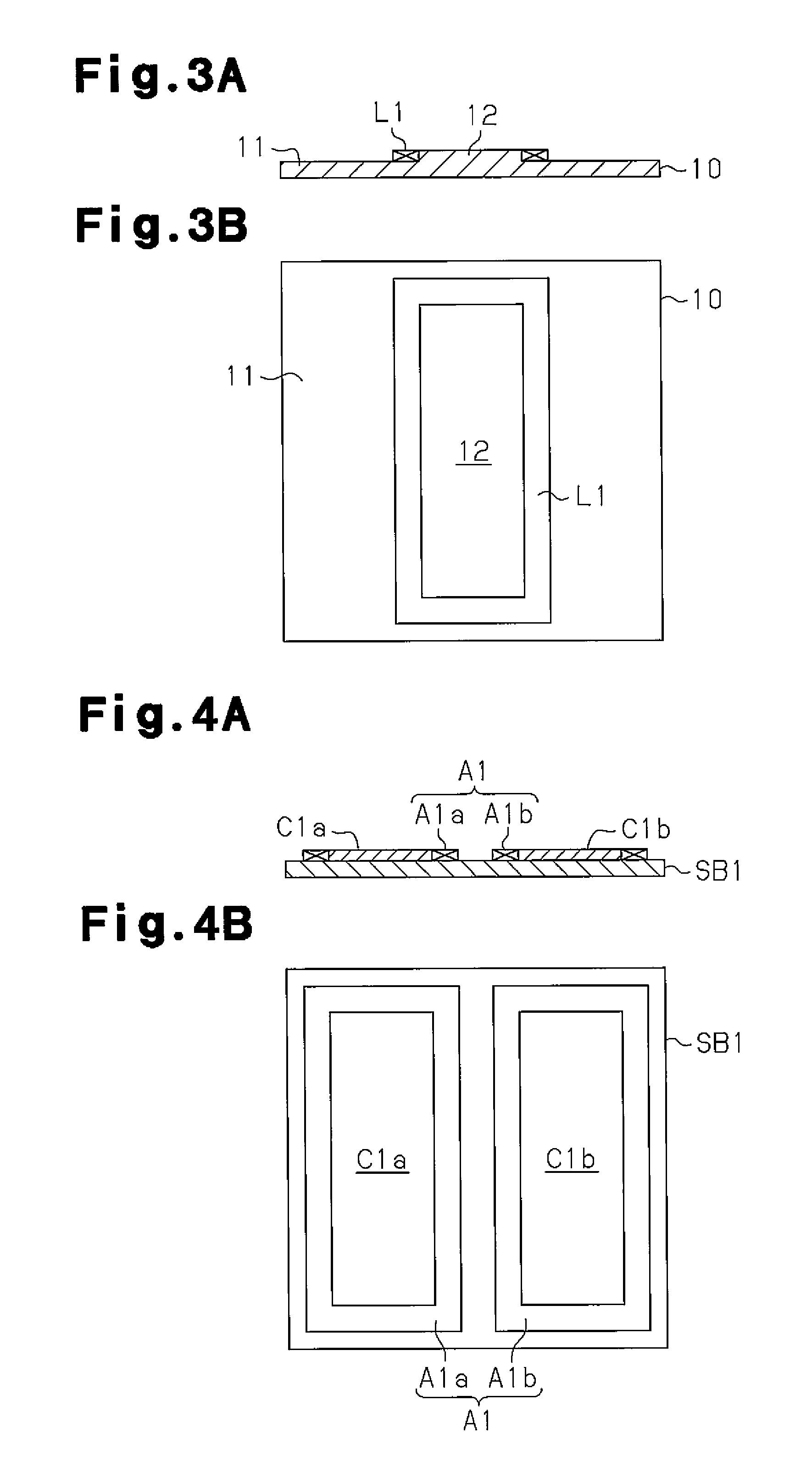
[0057]As illustrated in FIG. 2, a plurality of primary coils L1 are respectively arranged in the casing 2 at locations corresponding to the power supply areas AR1 to ...


PUM

PropertyMeasurementUnit
frequencyaaaaaaaaaa
frequencyaaaaaaaaaa
poweraaaaaaaaaa

Abstract

A contactless power supply system includes a power supply areas, each provided with a primary coil and a primary authentication coil. The primary coil and primary authentication coil are arranged at different locations. An electric appliance includes a power reception area provided with a secondary coil and a secondary authentication coil. The secondary coil and the secondary verification coil are arranged at different locations. The presence of a metal foreign object is detected between the primary coil and secondary coil based on a transmission oscillation signal generated by the primary coil, and the presence of a metal foreign object is detected between the primary authentication coil and secondary authentication coil based on an authentication oscillation signal generated by the primary authentication coil.

Description

TECHNICAL FIELD[0001]The present invention relates to a method for detecting a metal foreign object in a contactless power supply system, a contactless power supply device, a power reception device, and a contactless power supply system.BACKGROUND ART[0002]An electromagnetic induction type contactless power supply system is provided with contactless power supply device, which includes a primary coil, and a power reception device, which includes a secondary coil. When an electric appliance including a power reception device is set on a setting surface of a contactless power supply device, the contactless power supply device excites a power supply coil. This excites a power reception coil, which is arranged in the power reception device of the electric appliance, through electromagnetic induction. The power reception coil generates secondary power that is converted into DC power and supplied to a load of the electric appliance.[0003]When a metal foreign object is present between the c...

Claims


Application Information

Patent Timeline
Patent Type & Authority Applications(United States)
IPC IPC(8): H01F38/14H02J7/00
CPCH02J5/005H01F38/14G01V3/10H01M10/46H02J7/00045Y02E60/10H02J50/402H02J50/005H02J50/12H02J50/60H02J50/10
Inventor GOTO, HIROMICHI
Owner PANASONIC INTELLECTUAL PROPERTY MANAGEMENT CO LTD
Why Eureka
Try Eureka