High intensity discharge lamp with coiled wire ignition aid

a high intensity, wire-coiled technology, applied in the direction of gas discharge lamp details, electric discharge tubes, electrical apparatus, etc., can solve problems such as unacceptable performance, and achieve the effect of unacceptable performan

Inactive Publication Date: 2013-04-18
GENERAL ELECTRIC CO
View PDF4 Cites 2 Cited by
  • Summary
  • Abstract
  • Description
  • Claims
  • Application Information

AI Technical Summary

Benefits of technology

[0008]A need to reduce the Kr85 content in HID lamps exists, but such reduction could have serious consequence to discharge initiation or ignition, and consequently unacceptable performance. This invention describes a means to obviate this disadvantage of lowering the Kr85 gas content.
[0009]It should be appreciated that terms such as upper, lower, top, bottom, right, left, and the like are relative terms that will change with the orientation of the lamp. These terms are used for improving understanding in this disclosure and should not be used to limit the invention as defined in the claims.
[0010]A first general embodiment of this disclosure features a high intensity discharge lamp comprising an electrically insulating arc tube comprised of light transmissive material. Electrical conductors, (e.g., electrodes) are each spaced apart from each other inside the arc tube. A shroud comprised of light transmissive material encloses the arc tube. An electrically conductive frame member is disposed in an interior of the shroud and is electrically connected to one of the electrical conductors. An ignition aid is electrically attached to the frame member and comprises a coil of electrically conductive wire that is disposed around the arc tube. Another electrically conductive frame member is also disposed in the shroud, and is connected to the second electrode inside the arc tube.
[0011]Referring to specific features of the first embodiment, the arc tube can include a central portion and two smaller sized legs each of which extends from the central portion, the central portion forming a discharge region inside the arc tube. The coil of wire can be disposed around one of the legs. The wire can be welded to the frame member as a coil. The wire can also be welded to the frame member as an uncoiled portion that extends from the coil. The discharge region can comprise inert starting gas and a dose fill of, for example, mercury and metal halides. A starting gas as a mixture of argon gas and / or xenon gas, and Kr85 gas, present in the discharge region can have an activity concentration of not greater than 0.16 MBq / liter. The electrodes can include a first electrode attached to a usually short frame member to which voltage is applied and a second electrode; the frame member can be electrically connected to the second electrode within the arc tube and to the coil that is disposed around one of the legs but electrically insulated from the first electrode. In another aspect, each of two coils of wire are electrically attached to each of two frame members in electrical contact with each of two electrical conductors and are disposed around each of the legs having the electrical conductors at opposite potential to the coils of wire.
[0012]The frame wire members or the coil of wire can be comprised of a base metal selected from the group consisting of Nb, Mo, Ta, Pt, Re, W, Ni, Fe and combinations thereof, or a combination of any of the base metals with cladding comprised of one or more of the base metals. The coil can also be wrapped around one of the legs of the arc tube more than 360 degrees. The coil can also have non-circular loops. The wire of the coil can extend in loops around an axis that, for most of a length of the coil, extends transverse to a longitudinal direction in which the electrodes extend. This is, the wire is not uncoiled wire wrapped around an arc tube leg to form a coil wherein the axis of the coil extends in a direction that the electrodes extend.
[0013]A second embodiment is the same as the first embodiment except that the arc tube is described more narrowly. The arc tube includes a central portion and two smaller sized legs each of which extends from said central portion, the central portion forming a discharge region inside the arc tube. In addition, the coil of wire is disposed around one of the legs. Any of the specific features described above with regard to the first embodiment can apply in any combination to the second embodiment.

Problems solved by technology

A need to reduce the Kr85 content in HID lamps exists, but such reduction could have serious consequence to discharge initiation or ignition, and consequently unacceptable performance.

Method used


Image

  • High intensity discharge lamp with coiled wire ignition aid
  • High intensity discharge lamp with coiled wire ignition aid
  • High intensity discharge lamp with coiled wire ignition aid

Examples


Embodiment Construction

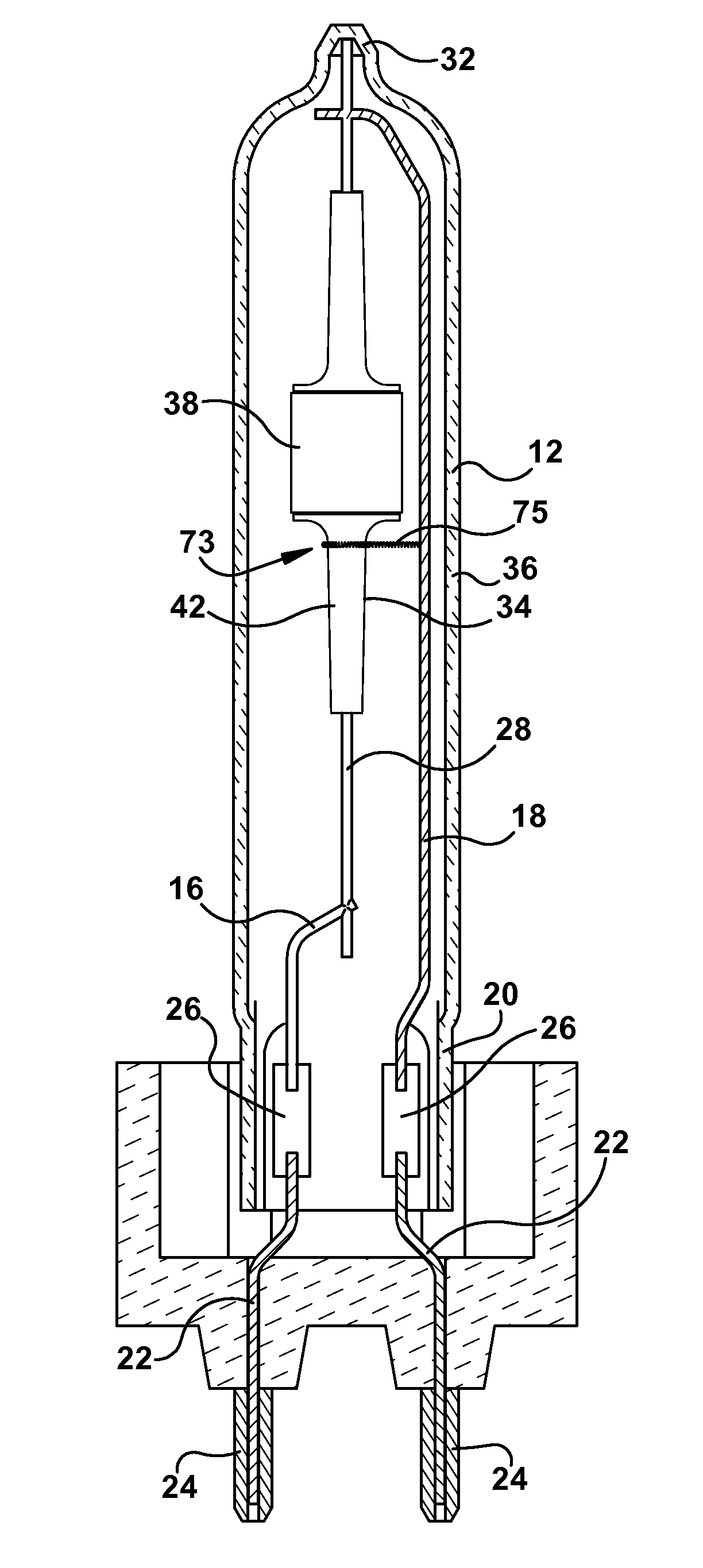
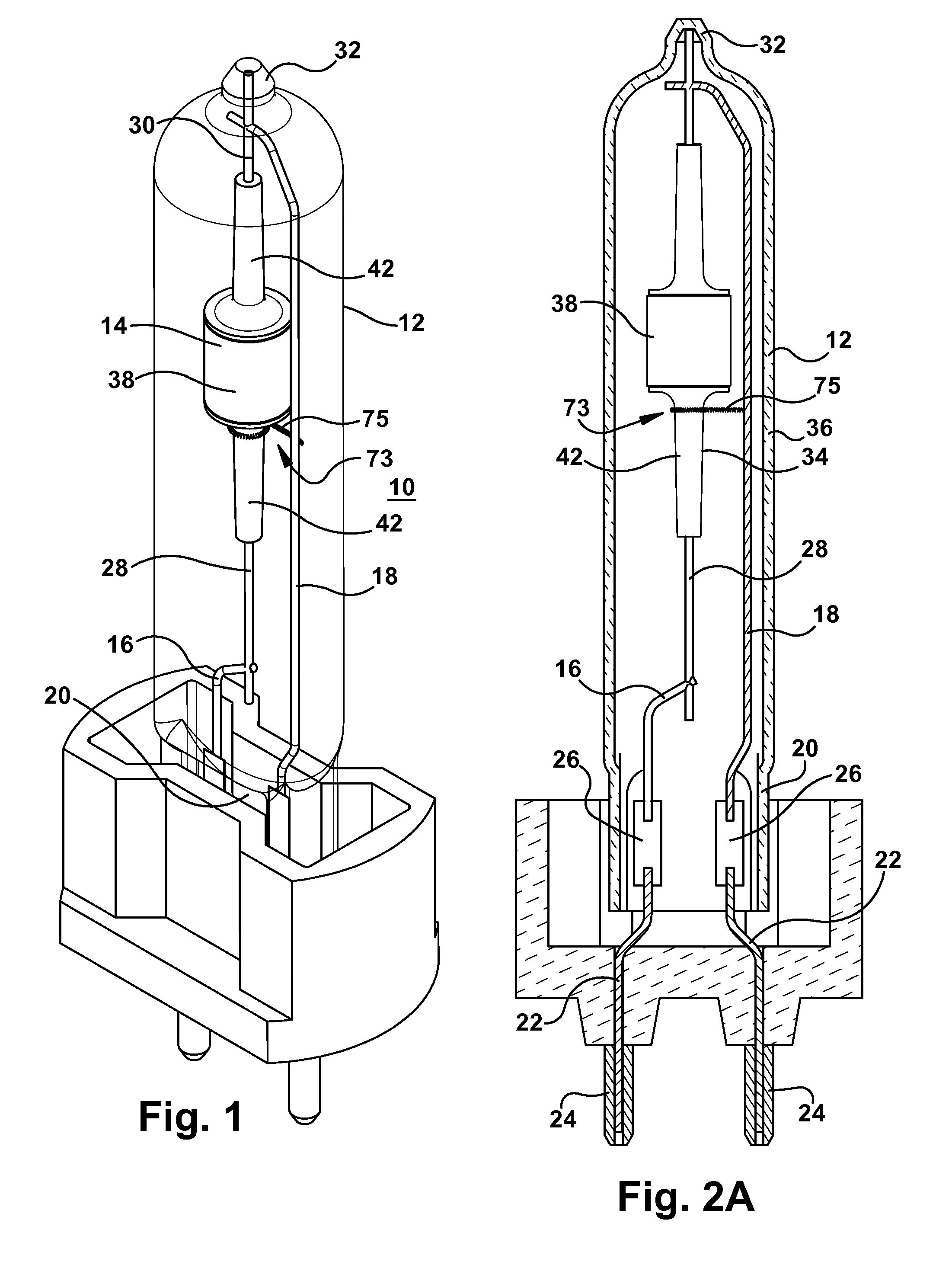
[0026]Referring to FIG. 1 and FIG. 2A, a ceramic metal halide high intensity discharge lamp 10 includes an outer shroud or bulb 12 enclosing an arc tube 14. This is a single ended lamp in that electrical contacts are located on only one end of the lamp. Electrically conductive frame members or wires 16, 18 are embedded in a glass pinch portion 20 at one end of the outer bulb 12. Leads 22 extending from contact pins 24 external to the outer bulb 12 are electrically connected to the frame wires 16, 18 by electrically conductive foil 26 located in the pinch portion 20. Each foil 26 is welded to one of the leads 22 and to one of the frame wires 16, 18. Electrically conductive feedthroughs 28, 30 extend into each end of the arc tube. The lower feedthrough 28 is welded to the short frame member 16 while the upper feedthrough 30 is welded to the long frame member 18. The upper feedthrough 30 extends upwardly past the connection with the long frame member 18 and is retained in place by bein...


PUM


Abstract

This disclosure features a high intensity discharge lamp comprising an electrically insulating arc tube comprised of light transmissive material. Electrical conductors or electrodes are each spaced apart from each other inside the arc tube. A shroud comprised of light transmissive material encloses the arc tube. An electrically conductive frame member is disposed in an interior of the shroud and is electrically connected to one of the electrical conductors. An ignition aid is electrically attached to the frame member and comprises a coil of electrically conductive wire that is disposed around the arc tube.

Description

FIELD OF THE INVENTION[0001]This disclosure relates to high intensity discharge lamps, and in particular, to ignition aids used in such lamps.BACKGROUND OF THE INVENTION[0002]Differences exist in speed of electric breakdown and the number of electrons needed to initiate a self-sustained electric discharge, but the underlying breakdown mechanism is the same for low pressure discharge lamps (e.g., fluorescent lamps) or high pressure discharge lamps (high intensity discharge lamps). Discharge is initiated between two conductors, the electrodes of the lamps, that are given opposite electric potential. The space between the electrodes usually comprises a starting gas, and efforts are made to maintain the quality / purity of the gas by enclosing it in a hermetic vessel. The essential end result of the discharge breakdown is the creation of a discharge plasma between the two electrodes. This early phase of discharge lamp operation is often called ignition of the lamp. Plasma is defined as a ...

Claims


Application Information

Patent Timeline
Patent Type & Authority Applications(United States)
IPC IPC(8): H01J61/04H01J61/20H01J61/16
CPCH01J61/34H01J61/827H01J61/547
Inventor BOROCZKI, AGOSTON
Owner GENERAL ELECTRIC CO
Why Eureka
Try Eureka