Lighting device

a technology of light source and light source, which is applied in the direction of vehicle headlamps, light and heating apparatus, transportation and packaging, etc., can solve the problems of low distance of light source arranged on a commonly switched carrier, the problem of affecting the uniformity of light source, and the failure to show an optimal distance in reference to each other, etc., to achieve convenient and cost-effective production, advantageous optic quality, and high homogeneity

Inactive Publication Date: 2013-04-18
HELLA KG HUECK & CO
View PDF5 Cites 9 Cited by
  • Summary
  • Abstract
  • Description
  • Claims
  • Application Information

AI Technical Summary

Benefits of technology

[0008]The particular advantage of the invention comprises that the partial light beams of the individual light sources arranged like a matrix are widened in the optic elements em-bodied as light guiding rods of the widening optic unit and provided at the decoupling area for a largely homogenous light distribution. In the proximity of the decoupling area light spots (light gaps), which due to the distance of the individual light sources are formed when a widening of the partial light beams is waived, are considerably reduced and / or entirely avoided. This is caused in the lateral surfaces of the optic elements allocated to the individual light sources oriented perpendicular in reference to the level of the light generation of the light sources. They act as total reflection surfaces and ensure a homogenous light distribution over the entire cross section of the light guiding elements.
[0009]The core of the invention is to provide here a virtual light source by the narrow spatial combination of a plurality of light sources and the widening optic unit comprising a light distribution with high homogeneity at the emission area (decoupling area). With regard to lighting technology the light sources and the allocated widening optic unit form a unit.
[0010]According to a preferred embodiment of the invention the light guiding rods show identical cross-sectional geometries. The cross sections are particularly embodied as a polygon, wherein here an area can be covered without overlaps entirely and without any gaps using such polygons. Advantageously the light guiding rods can be placed particularly closely at each other when their cross sections can be briquetted. Here, the light spots (light gaps) are particularly small if no or only very little clear spaces remain between the light guiding rods. For example, the cross sections of the light guiding rods may be embodied triangularly or as even hexagons.
[0011]According to a further development of the invention the light guiding rods shows a rectangular, particularly square cross section. The lateral sides of the light guiding rods are aligned in pairs parallel in reference to each other. Advantageously the individual optic elements of the widening optic unit may be placed very closely to each other when a rectangular cross section is used. Additionally, optic elements with a rectangular cross section can be produced easily and cost-effectively.
[0012]According to a further development of the invention a common optic disk is allocated to the light guiding rods on a face thereof facing away from the light sources, with the optic disk comprising the decoupling area of the widening optic unit. Advantageously the optic quality and the homogeneity of the light distribution improves by the provision of the joint optic disk covering the individual optic elements at the facial side. Additionally the optic disk provides mechanic stability to the widening optic unit.
[0013]According to another further development a lens area is formed in the proximity of the facial side of the optic elements (coupling area) facing the light sources. Advanta-geously the optic effectiveness of the entire arrangement improves by the provision of the lens surface in the proximity of the light coupling area.

Problems solved by technology

Here, it is problematic that the plurality of light sources, which may be arranged for example like a matrix, generally fail to show an optimal distance in reference to each other considering technical lighting aspects.
If for example pre-assembled arrays are used showing several light sources, here the distance of the light sources arranged on a commonly switched carrier is frequently too low.
Although the use of the transparent light source has generally proven to be of value, an individual widening of the individual light beams can only occur to a limited extent for all light sources when a single joint light plate is provided.
Accordingly they are expensive in their production.
Furthermore, the optic elements to form the light are not or only to a limited extent suitable to widen the partial light beams, due to their design, and to realize a homogenous light emission area.

Method used


Image

  • Lighting device
  • Lighting device
  • Lighting device

Examples


Embodiment Construction

[0023]In the following detailed description numerous specific details are set forth in order to provide a thorough understanding of the invention. However, it will be understood by those skilled in the art that the present invention may be practiced without these specific details. For example, the invention is not limited in scope to the particular type of industry application depicted in the figures. In other instances, well-known methods, procedures, and components have not been described in detail so as not to obscure the present invention.

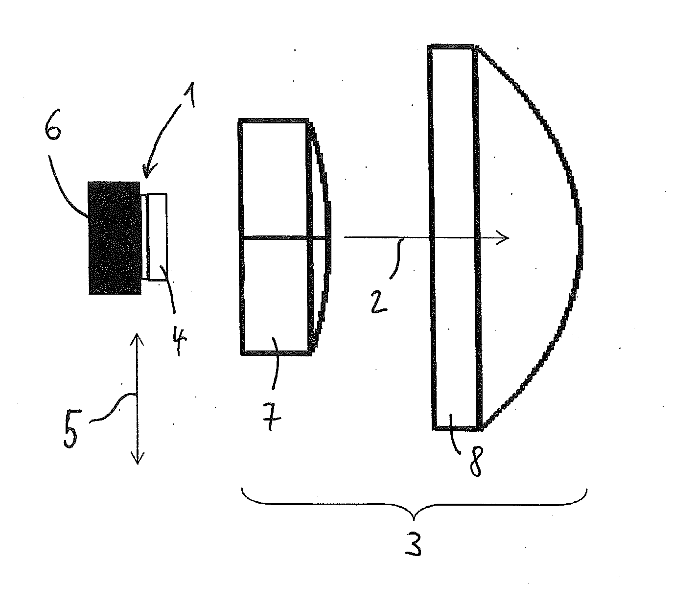
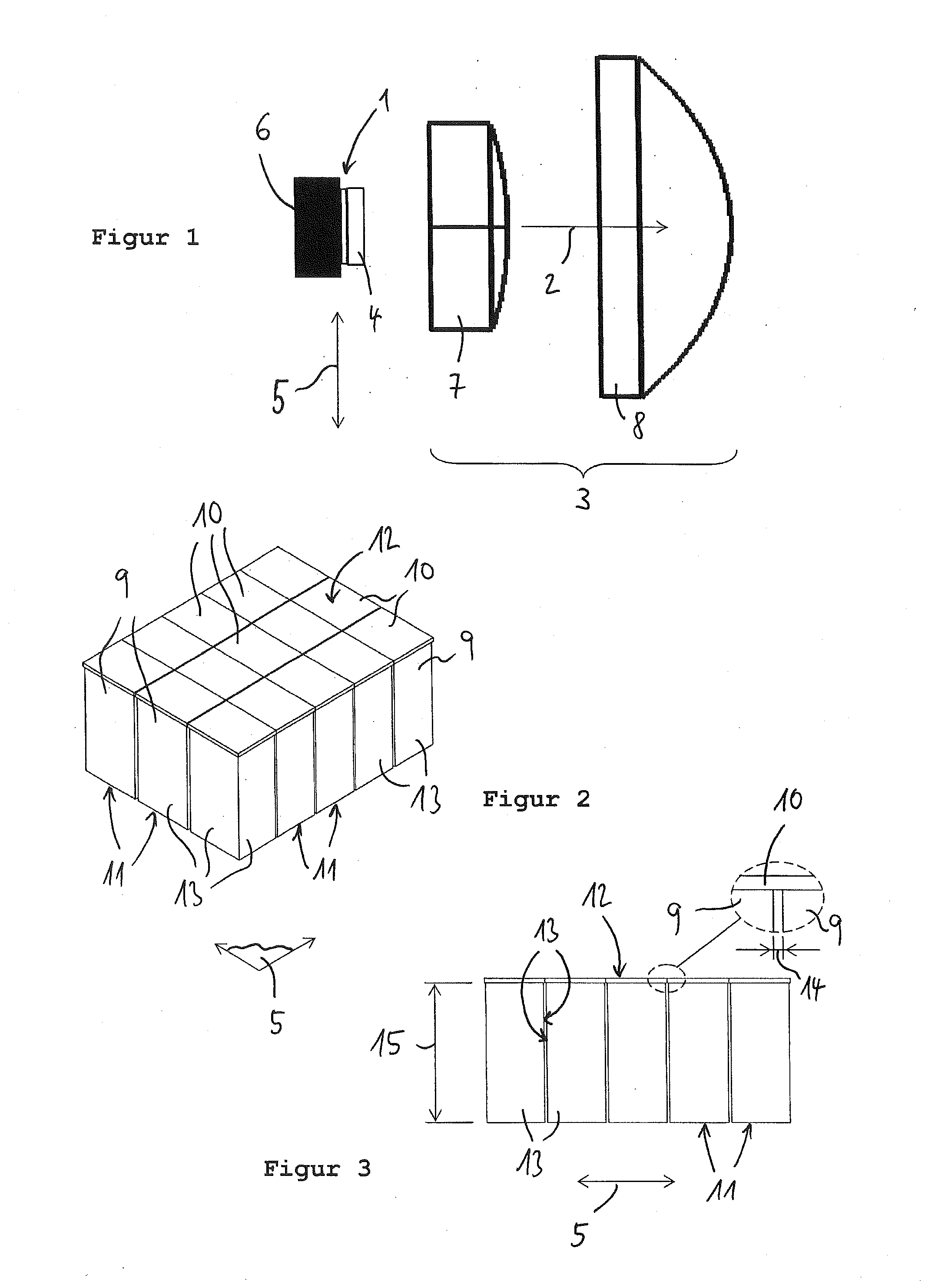
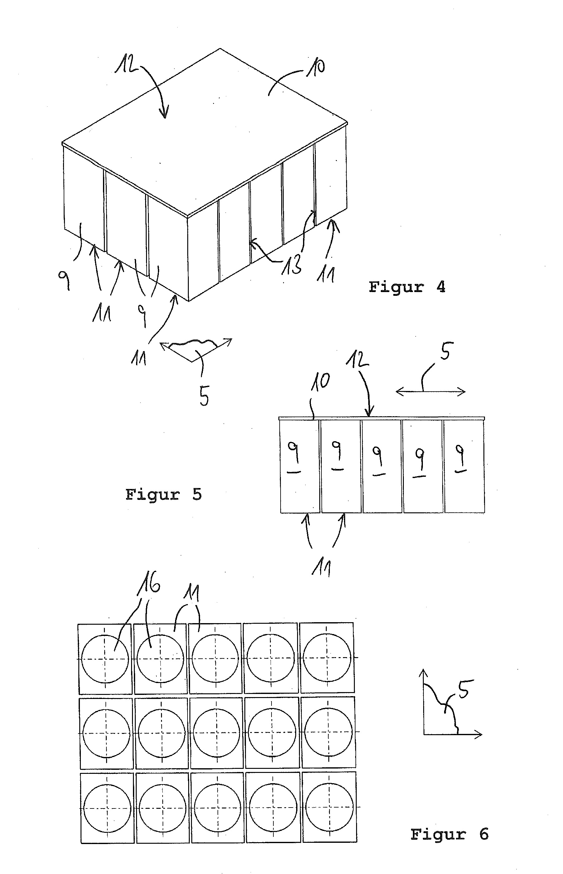
[0024]A lighting device according to FIG. 1 comprises a plurality of light sources 1, a light forming optic unit 3 located in front of the light sources 1 in a primary direction of emission 2 of the lighting device, as well as a widening optic unit 4 arranged between the light forming optic unit 3 and the light sources 1. The lighting device serves as the headlights of vehicles, for example. In particular it may be used to form controllable hig...


PUM


Abstract

A lighting device for vehicles with multiple light sources arranged like a matrix in one light generation level, with a light forming optic unit arranged in front of the light sources, and with another optic unit arranged between the light forming optic unit and the light sources, comprising a plurality of optic elements that are arranged like a matrix and one optic element each being allocated at a face thereof to a light source and with the other optic unit in front of the optic elements being allocated to the light sources to coupling areas and at least one decoupling area facing the light forming optic unit, with the other optic unit being embodied as a widening optic unit for widening the partial light bundles emitted by the light sources with light guiding rods as optic elements.

Description

CROSS REFERENCE[0001]This application claims priority to German Patent Application No. 10 2011 054 232.9, filed Oct. 6, 2011.TECHNICAL FIELD OF THE INVENTION[0002]The invention relates to a lighting device for vehicles with a plurality of light sources arranged like a matrix in a light generation level comprising a light forming optic unit arranged in front of the light sources seen in the primary direction of emission and with another optic unit arranged between the light forming optic unit and the light sources, comprising a plurality of optic elements, with the optic element being arranged like a matrix and one optic element each being allocated with its face to a light source and with the other optic unit comprising coupling surfaces in the area of the faces of the optic elements allocated to the light sources and at least one decoupling area facing the light forming optic unit.BACKGROUND OF THE INVENTION[0003]Today, increasingly lighting devices are created for vehicles which p...

Claims


Application Information

Patent Timeline
Patent Type & Authority Applications(United States)
IPC IPC(8): B60Q1/00F21W107/10
CPCB60Q1/00F21S48/1154F21S48/1241F21S48/1275F21S48/1747F21S48/1258F21S41/143F21S41/24F21S41/255F21S41/265F21S41/663F21S41/153
Inventor KLOOS, GERHARD
Owner HELLA KG HUECK & CO
Why Eureka
Try Eureka