Method for the microscopic three-dimensional reproduction of a sample

a three-dimensional reproduction and sample technology, applied in the field of three-dimensional reproduction of samples, can solve the problems of spim method, expensive and time-consuming, and the computer is usually not suitable for handling the required computing capacity, and achieves the effects of avoiding shadow effects, improving resolution, and improving the quality of green fluorescent proteins

Active Publication Date: 2013-04-18
CARL ZEISS MICROSCOPY GMBH
View PDF40 Cites 29 Cited by
  • Summary
  • Abstract
  • Description
  • Claims
  • Application Information

AI Technical Summary

Benefits of technology

[0018]Therefore, it is the object of the invention to provide method steps which ensure an enhanced imaging quality in the three-dimensional imaging of a sample.
[0055]The advantage of using a reference structure to assist in adjusting the light sheet and in acquiring the image information consists in that the reference structure is not dependent on the sample structure and is therefore less subject, or not at all subject, to the artifacts predominantly caused by the sample itself.
[0060]In both variants of the invention, the detection direction is preferably changed by rotating the sample relative to the detection direction defined by the detection objective. The purpose of this procedure is to avoid shadow effects or to achieve a more homogeneous resolution.
[0066]The amount of image information of the reference structure is less by orders of magnitude than the amount of image information of the sample. This substantially reduces the resources required for processing.
[0079]The essential advantages of using reference structures which originate from reference objects and which can also be impressed upon the illumination light consist in that, first, a simple in-situ adjustment of the light sheet is possible when applying selective plane illumination microscopy (SPIM) and, second, the computing effort in the reconstruction of the three-dimensional image of the sample is substantially reduced compared to the prior art when reference objects are used.

Problems solved by technology

One problem with this is that measurement is not carried out directly at the sample; another is that the adjustment is carried out at a laser wavelength which does not correspond to the emission wavelength coming from the sample, which is actually the wavelength of interest, so that any chromatic longitudinal errors, e.g., of the detection objective, are not taken into account.
The adjustment of the light sheet based directly on the sample is desirable, but a suitable method for this is not known from the prior art.
Another problem with the SPIM method becomes apparent when reconstructing three-dimensional images of a sample from image information acquired from different detection directions.
The registration, i.e., the acquisition of image information and the necessary operation rules, is then very costly and time-consuming, and commercially available computers are usually not suitable for handling the required computing capacity.

Method used


Image

  • Method for the microscopic three-dimensional reproduction of a sample
  • Method for the microscopic three-dimensional reproduction of a sample
  • Method for the microscopic three-dimensional reproduction of a sample

Examples


Embodiment Construction

[0087]It is to be understood that the figures and descriptions of the present invention have been simplified to illustrate elements that are relevant for a clear understanding of the present invention, while eliminating, for purposes of clarity, many other elements which are conventional in this art. Those of ordinary skill in the art will recognize that other elements are desirable for implementing the present invention. However, because such elements are well known in the art, and because they do not facilitate a better understanding of the present invention, a discussion of such elements is not provided herein.

[0088]The present invention will now be described in detail on the basis of exemplary embodiments.

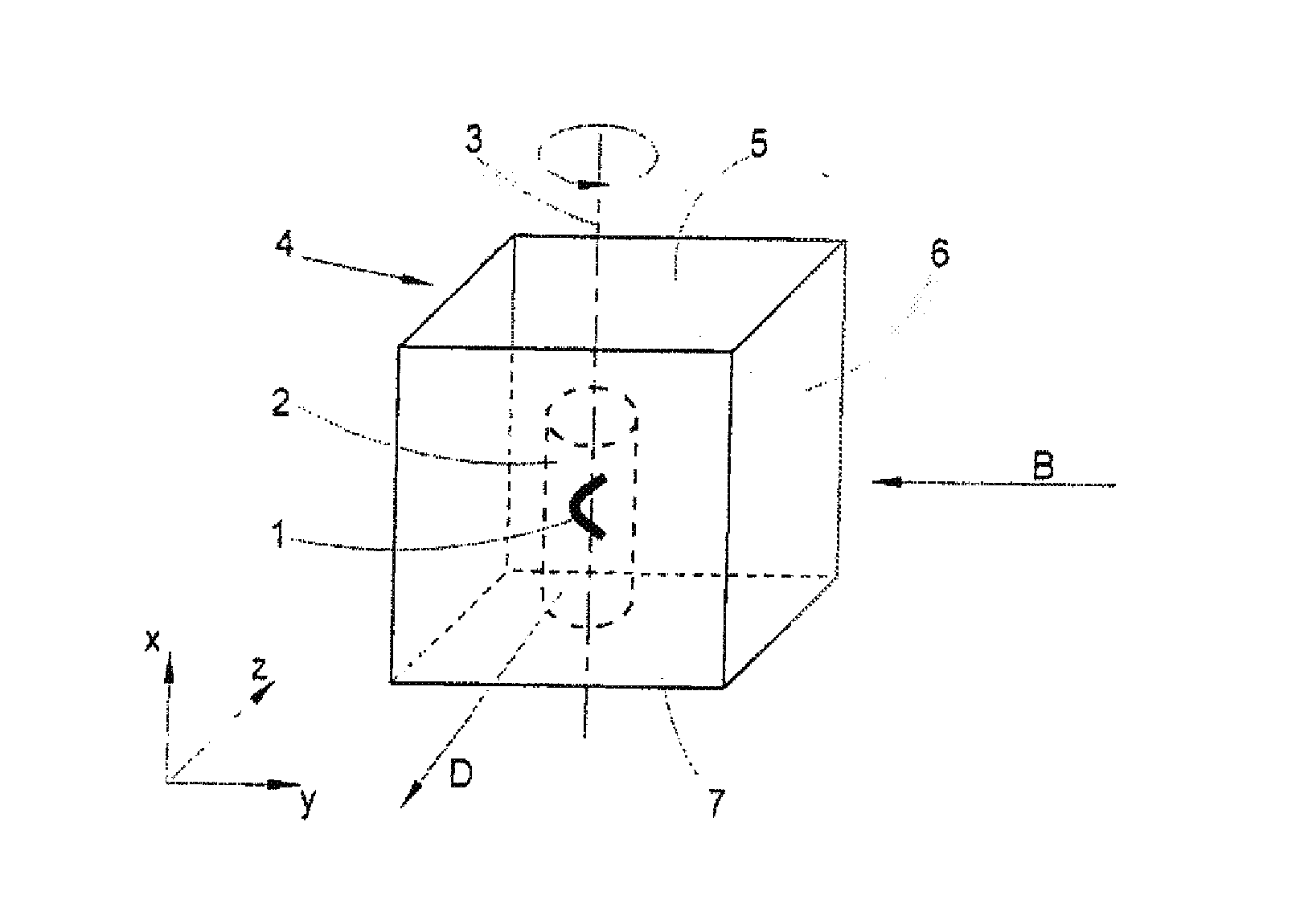
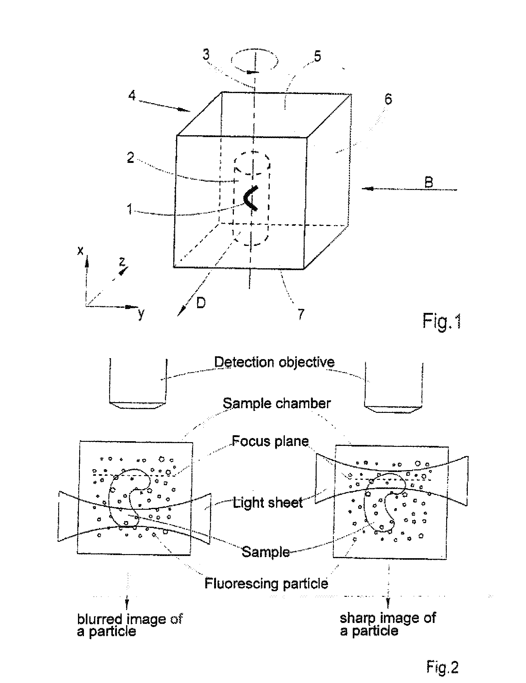
[0089]As can be seen from FIG. 1, a sample 1 is embedded in a gel which is shaped to form a circular cylinder 2. The circular cylinder 2 is located in a sample chamber 4 and is supported inside the sample chamber 4 so as to be rotatable around an axis of rotation 3 and displace...


PUM


Abstract

A method for the three-dimensional imaging of a sample in which image information from different depth planes of the sample is stored in a spatially resolved manner, and the three-dimensional image of the sample is subsequently reconstructed from this stored image information is provided. A reference structure is applied to the illumination light, at least one fluorescing reference object is positioned next to or in the sample, images of the reference structure of the illumination light, of the reference object are recorded from at least one detection direction and evaluated. The light sheet is brought into an optimal position based on the results and image information of the reference object and of the sample from a plurality of detection directions is stored. Transformation operators are obtained on the basis of the stored image information and the reconstruction of the three-dimensional image of the is based on these transformation operators.

Description

[0001]The present application is a divisional of U.S. patent application Ser. No. 12 / 680,056 filed on Mar. 25, 2010, which claims priority from PCT Patent Application No. PCT / EP2008 / 007686 filed on Sep. 16, 2008, which claims priority from German Patent Application No. 10 2007 045 897.7 filed on Sep. 26, 2007, the disclosures of which are incorporated herein by reference in their entirety.1. FIELD OF THE INVENTION[0002]The present invention relates to a system and a method for mutual authentication in which a higher-level device and a lower-level device mutually authenticate each other.[0003]The invention is directed to a method for the three-dimensional imaging of a sample in which image information from different depth planes of the sample is acquired from at least one detection direction and is stored in a spatially resolved manner, i.e., correlated to its spatial coordinates X, Y, Z, and in which the three-dimensional image of the sample is subsequently reconstructed electronica...

Claims


Application Information

Patent Timeline
Patent Type & Authority Applications(United States)
IPC IPC(8): G06T7/00
CPCG02B21/002G06T7/0022G02B21/367G02B21/244G06T7/97
Inventor LIPPERT, HELMUTRADT, BENNOKEMPE, MICHAELDIETRICH, CHRISTIAN
Owner CARL ZEISS MICROSCOPY GMBH
Why Eureka
Try Eureka