Passive Fireproofing System for Pipelines

a fireproofing system and pipeline technology, applied in the direction of paper/cardboard containers, paints with biocides, weaving, etc., can solve the problems of pipelines made of materials with good thermal conductivity such as steel and metal pipes, and cannot be realized without additional procedures

Inactive Publication Date: 2013-04-18
HILTI AG
View PDF6 Cites 13 Cited by
  • Summary
  • Abstract
  • Description
  • Claims
  • Application Information

AI Technical Summary

Problems solved by technology

However, even if no flames spark over, fire can still develop in a room if the heat on the side of the wall facing away from the fire rises in temperature to the point where combustible materials self-ignite.
In particular, pipelines made of materials with good thermal conductivity such as steel and metal pipes are a problem in this respect.
If this is the case, it can result in ignition and hence a fire is started on the side facing away from the fire.
Especially for feedthroughs of non-insulated line legs, in particular, pipes or conduits such as metal pipes through walls and ceilings, this cannot be realized without additional procedures, because the metal pipes or conduits transmit the heat through the bulkhead to the other side of the wall in spite of the bulkheading of the feedthrough due to their good thermal conductivity.
As a result, the materials surrounding the pipe or adjacent to the pipe are also heated up, which can lead to the spreading of the fire when the respective ignition temperature is exceeded, in spite of the bulkheading of the feedthrough.
The heat transmission through the wall or ceiling via pipelines is notable with thin walls and ceilings such as retroactively installed drywalls because the wall and ceiling thickness and the material they are made of is often inadequate to remove the heat from the heated pipeline.
The disadvantage of this solution is that a separate collar and a separate cooling aggregate with a corresponding circumference are required for every pipe circumference.
This considerably increases the work and material expenditures.
The disadvantages of coatings include that they are expensive, difficult to apply and sensitive to mechanical stress or impact, and that their thermal conductivity is relatively low.

Method used


Image

  • Passive Fireproofing System for Pipelines
  • Passive Fireproofing System for Pipelines
  • Passive Fireproofing System for Pipelines

Examples


Embodiment Construction

[0020]Some embodiments provide a universal system that is easy to handle (e.g., can be easily adjusted to the different geometries of the line legs to be enveloped) and that is easy to adjust to the designed length. Some embodiments provide a universal system that is manufactured and processed economically, is harmless to the environment in the case of a fire and meets the applicable fireproofing regulations.

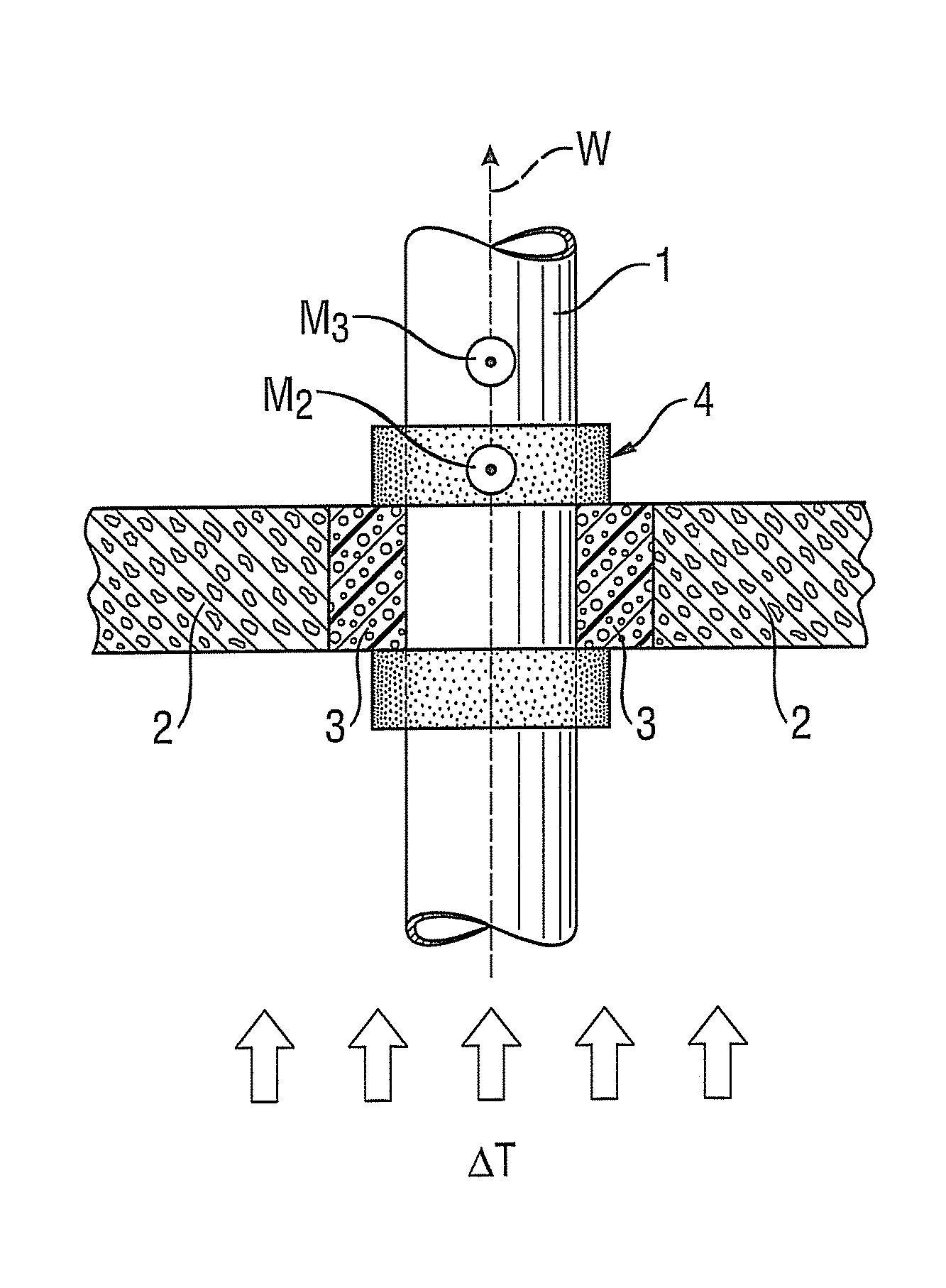
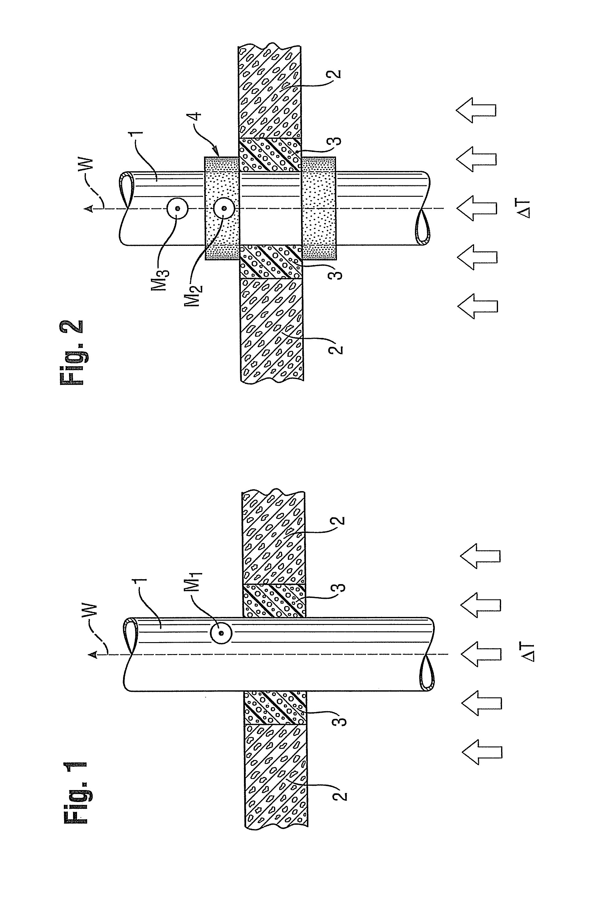
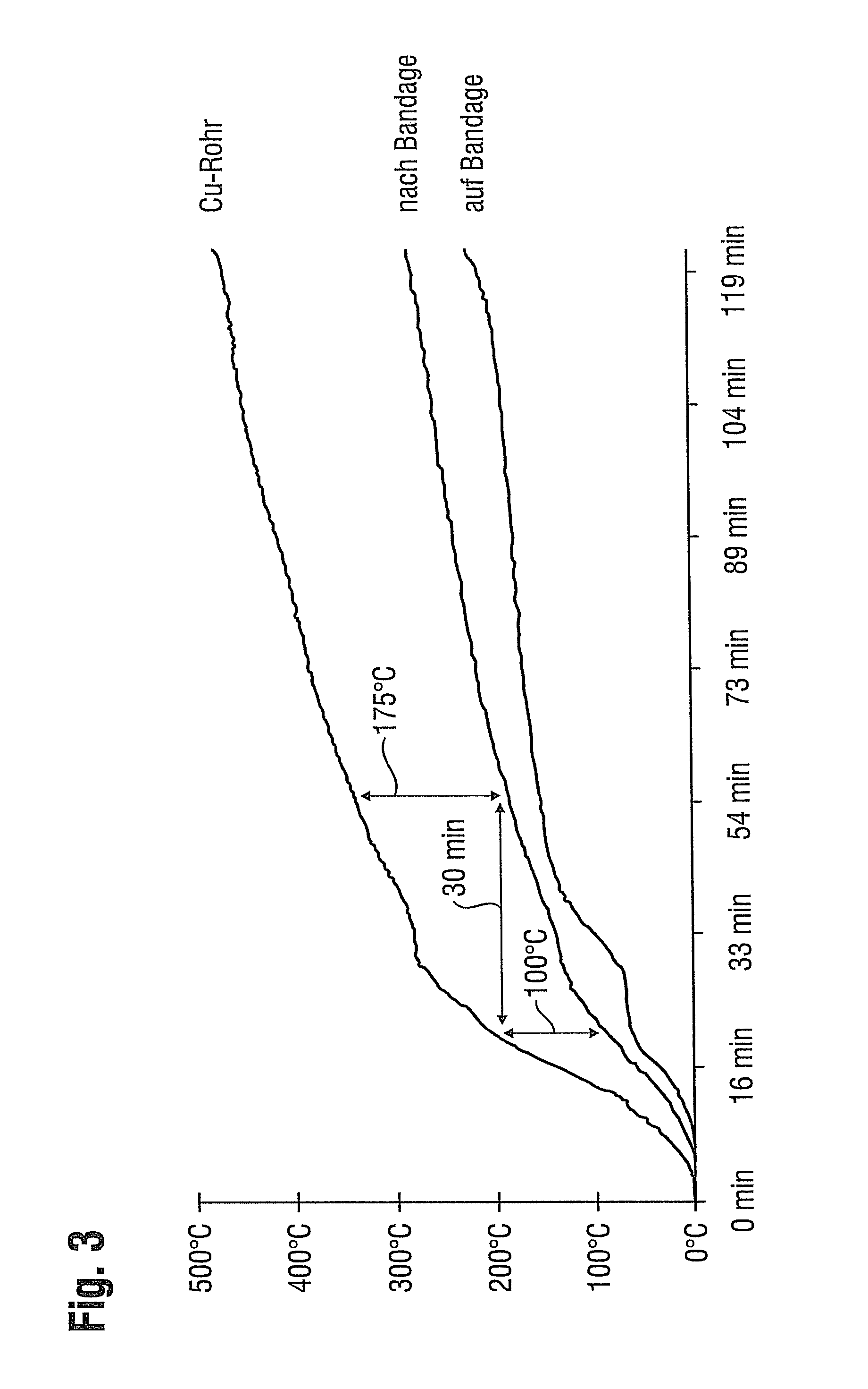
[0021]Some embodiments provide a lining that is wrapped around the line leg immediately subsequent (e.g., adjacent) to the bulkheading of the feedthrough opening in the component on both sides of wall feedthroughs and / or above the feedthrough opening of ceiling feedthroughs. The lining is capable of cooling the line leg if the temperature rises.

[0022]The term critical temperature used within the meaning of the invention means a temperature that exceeds the room or ambient temperature by more than 180 K. For a room temperature of 22° C., the critical temperature would be 202° C. ...


PUM

PropertyMeasurementUnit
temperatureaaaaaaaaaa
critical temperatureaaaaaaaaaa
temperatureaaaaaaaaaa

Abstract

A lining and a related method for extending the period during which a line leg, such as a pipeline in a fireproofing installation, remains below a critical temperature are described. The lining includes, for example, a binding agent, endothermically degradable fillers and / or other fillers, if applicable. The method includes a wrapped line leg with the lining on both sides for wall feedthroughs and / or above the feedthrough opening for ceiling feedthroughs directly after the bulkheading of a feedthrough opening in a fireproofing installation. The heat removal from or the cooling of a line leg can be supported easily and applied on-site in such a way that even line legs with good thermal conductivity can achieve a high T-rating value in the fire test.

Description

CROSS-REFERENCE TO RELATED APPLICATIONS[0001]The present application claims priority to German Patent Application No. DE 10 2011 080 329.7, filed Aug. 3, 2011, which is hereby incorporated by reference in its entirety.FEDERALLY SPONSORED RESEARCH OR DEVELOPMENT[0002][Not Applicable]MICROFICHE / COPYRIGHT REFERENCE [0003][Not Applicable]BACKGROUND OF THE INVENTION[0004]Openings are provided in components in order to lead line legs such as conduits or pipelines through components such as walls, ceilings, etc. In many countries, the set-up of so-called fireproofing areas is required by law for special buildings including public buildings, hospitals, schools, etc. This is aimed at preventing the fire and the associated flue gases from spreading rapidly through the entire building in case of fire. Therefore, the openings must be sealed fire-proof and flue gas-proof to prevent the fire or flue gas from passing through the opening. A number of devices for the fire-proof and flue gas-proof fe...

Claims


Application Information

Patent Timeline
Patent Type & Authority Applications(United States)
IPC IPC(8): C09D5/18
CPCC09D5/18F16L57/04F16L59/145Y10T156/10F16L55/1026H02G3/0412H02G3/22F16L5/04Y10T428/23986Y10T442/2631D06N2209/067D06N2201/08D06N2209/065D06N3/0063
Inventor MUNZENBERGER, HERBERT
Owner HILTI AG
Why Eureka
Try Eureka