

Enclosure and mount for motion capture element
a technology of motion capture element and mount, which is applied in the field of mounting, can solve the problem that the piece of equipment cannot be instrumented, and achieve the effect of easy removal and replacemen
- Summary
- Abstract
- Description
- Claims
- Application Information
AI Technical Summary
Benefits of technology
Problems solved by technology
Method used
Image

Examples
Embodiment Construction
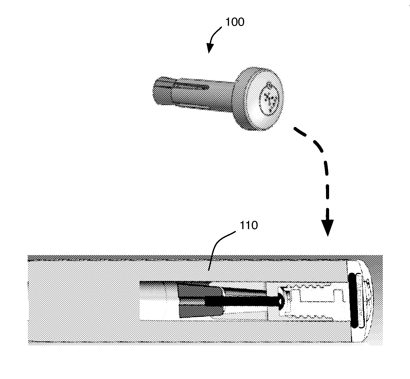
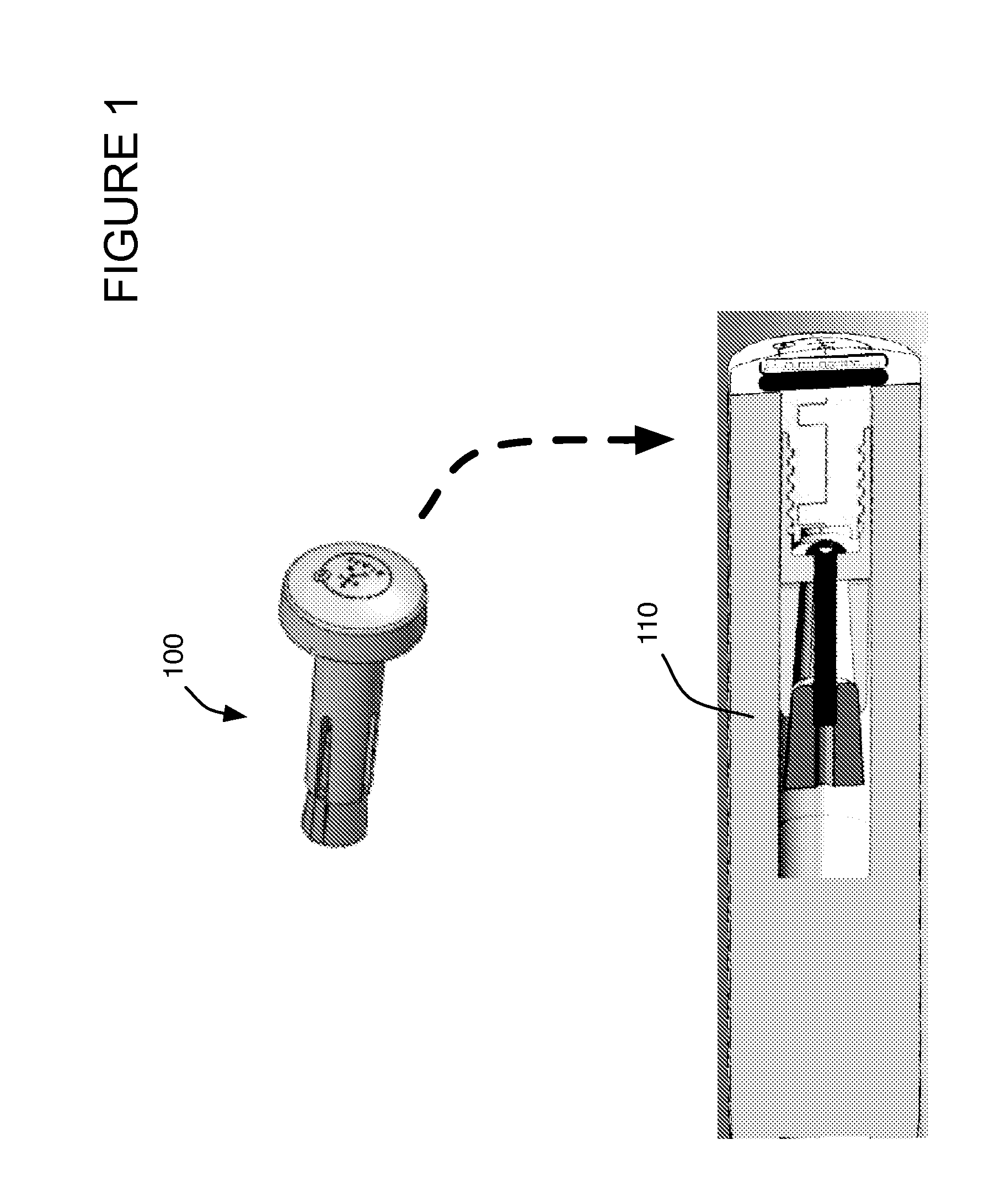
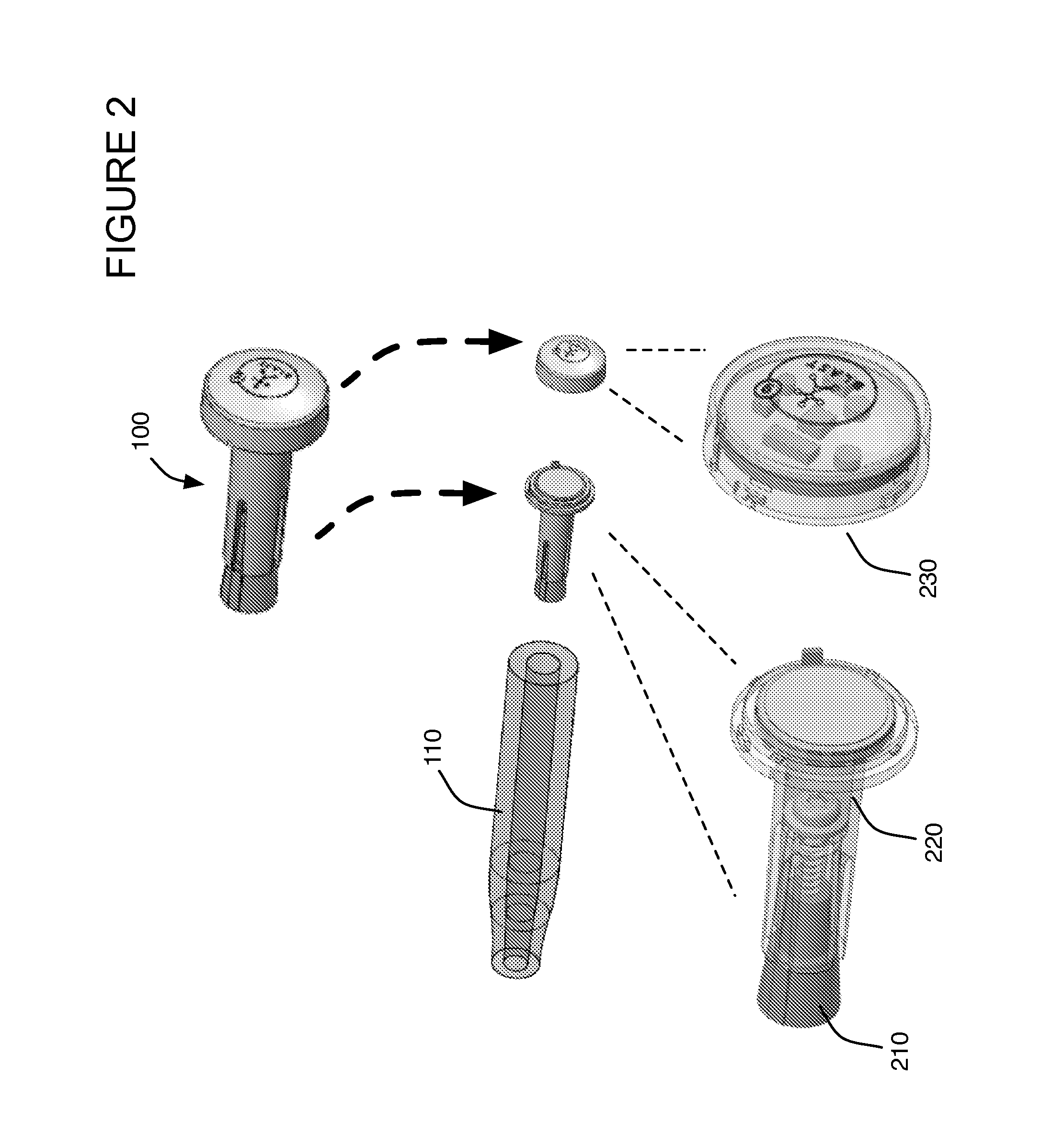
[0057]An enclosure and mount for motion capture element will now be described. In the following exemplary description numerous specific details are set forth in order to provide a more thorough understanding of the ideas described throughout this specification. It will be apparent, however, to an artisan of ordinary skill that embodiments of ideas described herein may be practiced without incorporating all aspects of the specific details described herein. In other instances, specific aspects well known to those of ordinary skill in the art have not been described in detail so as not to obscure the disclosure. Readers should note that although examples of the innovative concepts are set forth throughout this disclosure, the claims, and the full scope of any equivalents, are what define the invention. One skilled in the art will recognize that embodiments of the invention may be utilized in any equipment capable of coupling with the apparatus. This includes any piece of sporting, exer...
PUM
 Abstract
Description
Claims
Application Information