Automatic Cleaning Machine for Wall Plates

a wall plate and automatic cleaning technology, applied in carpet cleaners, building repairs, cleaning using liquids, etc., can solve the problem of increasing labor costs and achieve the effect of reducing labor costs

Inactive Publication Date: 2013-04-25
LIAO FU CHANG
View PDF0 Cites 51 Cited by
  • Summary
  • Abstract
  • Description
  • Claims
  • Application Information

AI Technical Summary

Benefits of technology

[0008]The present invention provides an automatic clea

Problems solved by technology

However, both the above methods of cleaning a building's exterior a

Method used


Image

  • Automatic Cleaning Machine for Wall Plates
  • Automatic Cleaning Machine for Wall Plates
  • Automatic Cleaning Machine for Wall Plates

Examples


first embodiment

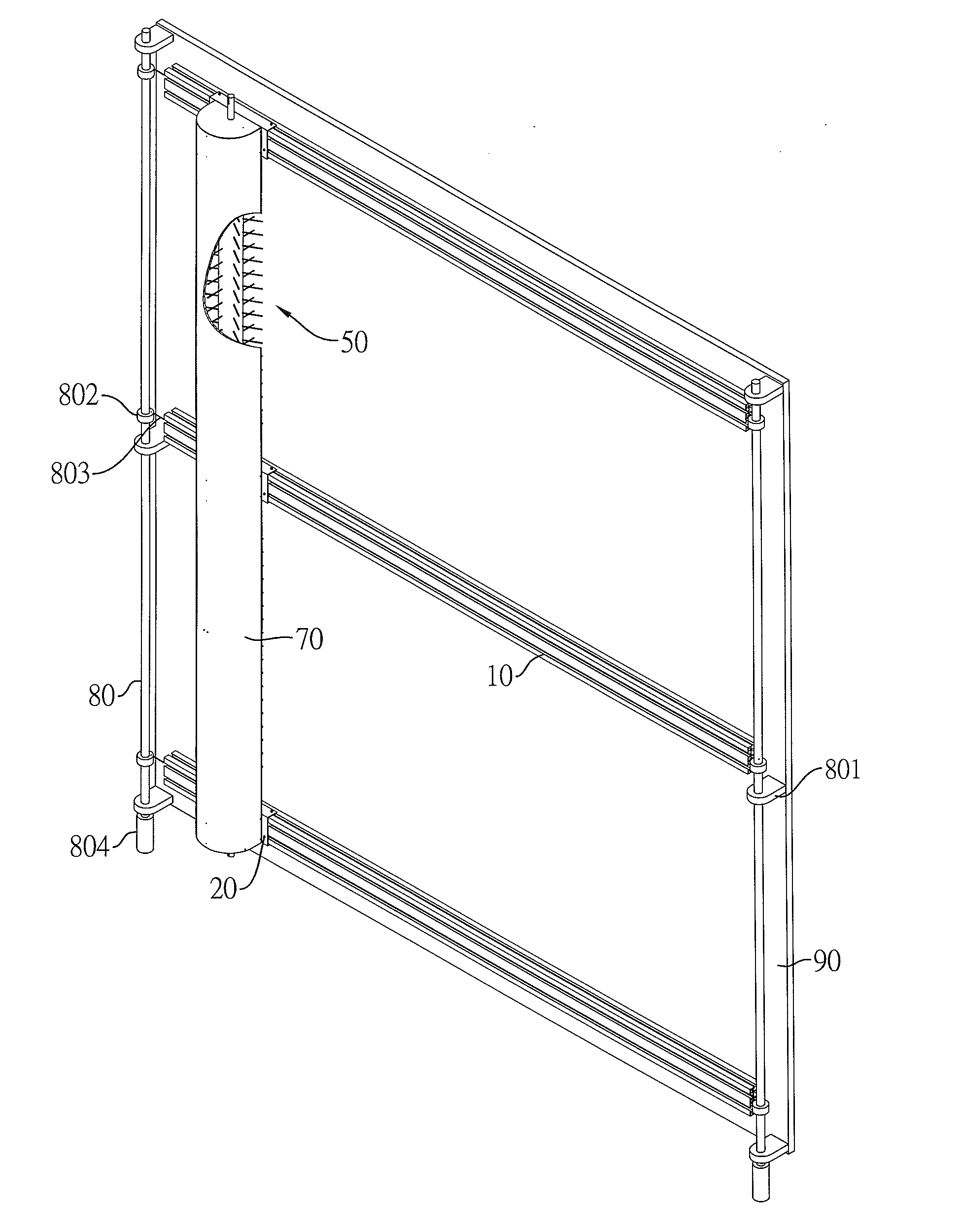
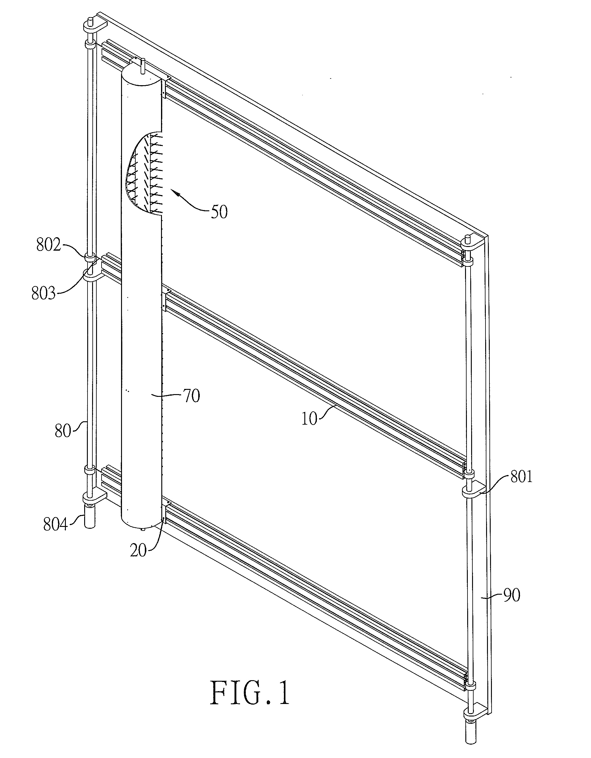
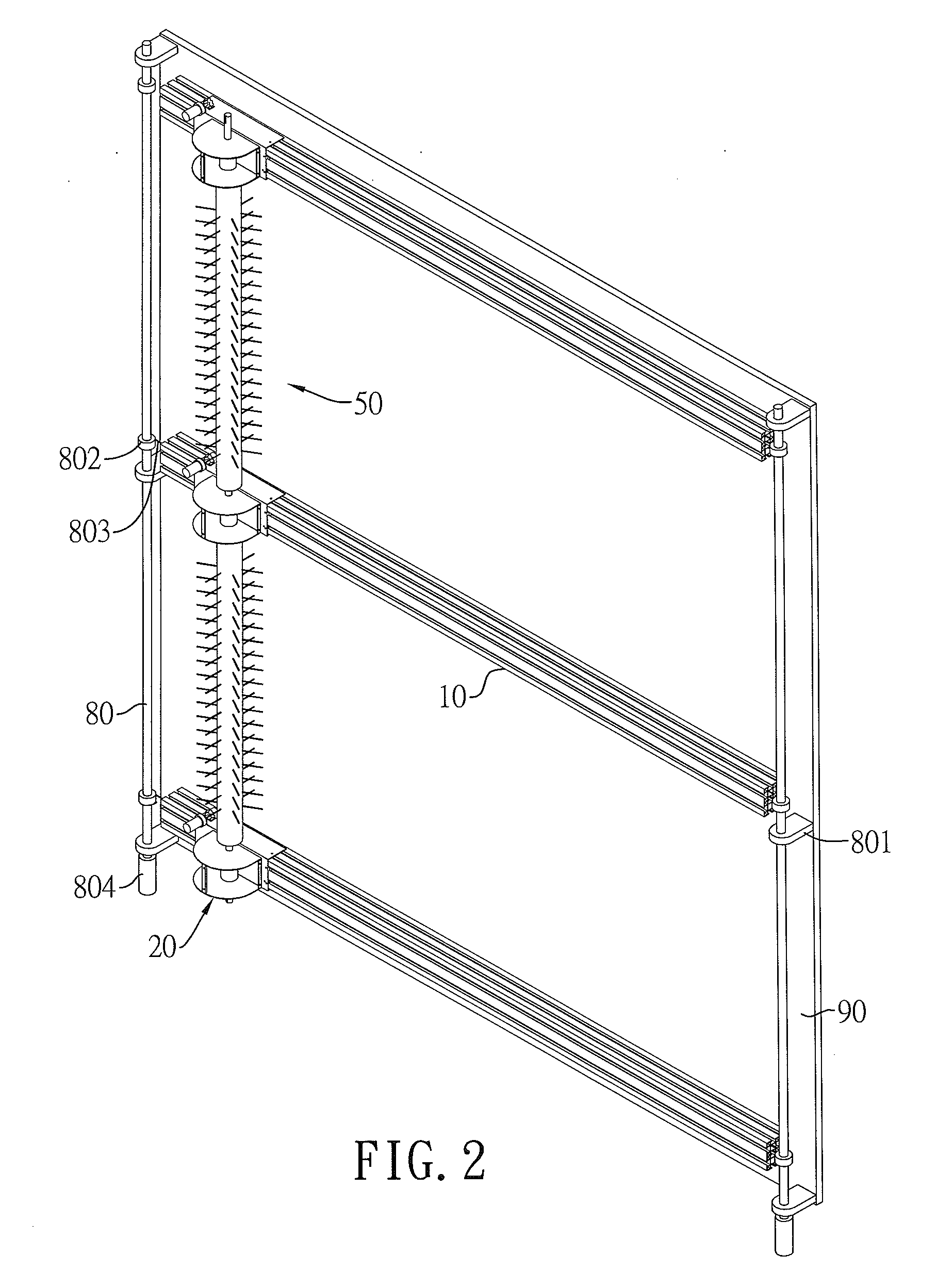
[0037]With reference to FIGS. 1 to 3, an automatic cleaning machine for wall plates in accordance with the present invention comprises at least two long axial tracks 10, a plurality of magnetic valves 30, at least two sliding frames 20, at least two bristle drive mechanisms 60, at least one long axial brush 50 and a cover plate 70.

[0038]With reference to FIGS. 3 and 5, each long axial track 10 is a rectangular aluminum extrusion and includes four side surfaces, a longitudinal water-guiding pipe 101, three longitudinal roller rails 102, a longitudinal fastening groove 103, a longitudinal electric rail mounting groove 104, a longitudinal magnet rail 105, a longitudinal magnetic valve mounting groove 106 and a longitudinal toothed strip mounting groove 107. Each roller rail 102 is formed in one of the side surfaces of the long axial track 10. An electric rail 1041 is secured in the electric rail mounting groove 104 and has one end electrically connected to a power supply. The magnet ra...

second embodiment

[0047]the present invention comprises at least two long axial tracks 10, a plurality of magnetic valves 30, at least two sliding frames 20, at least two bristle drive mechanisms 60B, at least one long axial brush 50B and a cover plate 70B.

[0048]With reference to FIG. 4, the magnetic valve 30 of the second embodiment is the same as the magnetic valve 30 of the first embodiment and thus a detailed description thereof will be omitted.

[0049]With reference to FIGS. 3, 5, 10 and 11, the long axial track 10 and the sliding frame 20 of the second embodiment are the same as the long axial track 10 and the sliding frame 20 of the first embodiment and thus detailed descriptions thereof will be omitted.

[0050]With reference to FIG. 10, each bristle drive mechanism 60B, which may be cylindrical in shape, is a pneumatic or electric linear actuator and includes two ends and a longitudinally reciprocating shaft lever 601B. The longitudinally reciprocating shaft lever 601B is vertical to the long axi...


PUM


Abstract

An automatic cleaning machine for wall plates is disclosed. Multiple long axial tracks with the same direction are fixed in a parallel and array pivoted way on the circumference or the plate face of the object to be cleaned. Water-guiding pipes are formed on the long axial tracks which are provided with electric rails, and multiple magnetic valves are provided on the pipe walls of the water-guiding pipes in a spaced way. The long axial tracks are provided with sliding frames. The sliding frames are provided with conducting brackets corresponding to the electric rails, and provided with long axial magnetic-attracted bodies opposed to the magnetic valves to turn on or off the cleaning water with a magnetic force. Brush drive mechanisms are provided on the sliding frames, and the shaft levers of the brush drive mechanisms are arranged in a direction normal to the long axial tracks and combined with long axial brushes to scrub wall plates. Cover plates are provided outside the long axial brushes. The automatic cleaning machine can be used for cleaning the plate faces of external walls, glasses and solar panels.

Description

CROSS REFERENCE TO RELATED APPLICATION[0001]This application is a National Stage of International Application No. PCT / CN2010 / 000987, filed Jun. 30, 2010, which is incorporated herein by reference in its entirety.BACKGROUND OF THE INVENTION[0002]1. Field of the Invention[0003]The present invention relates to a cleaning device, and more particularly to a cleaning device for automatically cleaning a wall plate.[0004]2. Description of the Related Art[0005]Exterior cleaning is the process of cleaning the exterior walls or windows of a building, thereby maintaining the cleanliness of the building's exterior. A typical method of cleaning a building's exterior is by supporting maintenance personnel on a suspended scaffold as the maintenance personnel manually clean the building's exterior.[0006]Solar panel cleaning is the process of cleaning a solar panel, thereby maximizing solar panel efficiency. A typical method of cleaning a solar panel is done manually by maintenance personnel.[0007]Ho...

Claims


Application Information

Patent Timeline
IPC IPC(8): B08B1/00
CPCA47L1/02B08B1/008B08B1/04F24J2/461E04G23/004Y02E10/40A46B13/02E04G23/002B08B1/002F24S40/20A47L11/38B08B3/02
Inventor LIAO, FU-CHANG
Owner LIAO FU CHANG
Why Eureka
Try Eureka