Mobile log splitter and pivoting conveyor: two-in-one

Inactive Publication Date: 2013-04-25
SHAEFFER LOUIS MARTIN
View PDF5 Cites 9 Cited by
  • Summary
  • Abstract
  • Description
  • Claims
  • Application Information

AI Technical Summary

Benefits of technology

[0012]There are two engines and two control panels present in the claimed invention. The two engines are supplied with separate fuel tanks, but share a single hydraulic fluid reservoir. The larger engine pressurizes hydraulic fluid and directs it to the upper control panel. By rotating the levers on the upper control panel, the operator can further direct the pressurized fluid to the hydraulic cylinders of the splitting ram, the log lifter, and the splitting head. Similarly, the smaller engine serves the purpose of pressurizing hydraulic fluid and directing it to the lower control panel. By rotating the levers and switches on the lower control panel, the operator can further direct the pressurized fluid to the hydraulic turbine of the conveyor driveshaft, as well as to the hydraulic cylinder of the rear foot, and to the hydraulic cylinder responsible for heightening the conveyor. All used hydraulic fluid is filtered and returned to the hydraulic fluid reservoir to be recycled through the various hydraulic systems of the machine.
[0013]The conveyor and log splitter components are both mounted on the same trailer axle and are thusly towable as one unit. Once the jobsite has been reached, the unit can be unhitched from the towing vehicle by manually extending the front foot through use of a hand crank. After the engines are started, the telescoping rear foot can be extended, giving the machine a fourth point of stationary support. Next, the operator can manually pivot the entire conveyor frame from is resting position on the trailer axle, to its operational position, in line with the rear of the machine. This action is possible because the conveyor frame is hinge-connected to the log splitter frame. Once the conveyor frame has been locked into place by a bolt, the heightening cylinder can be extended until the upper end of the conveyor is at the desired height, and production of firewood can begin. When it becomes time to relocate the machine around the jobsite, the operator does not need to change the position of the conveyor in any way. To relocate the machine, the operator needs to first check that the log lifter device is in its raised position. At this point, the rear foot can be retracted and the unit can be hitched to the towing vehicle by manually raising the front foot via rotation of the hand crank. The unit can then be towed to the new on-site location, unhitched from the vehicle, and immediately returned to operation. Th

Problems solved by technology

Perhaps the largest source of inefficiency in this process is the occurrence of events which prevent the continual splitting of logs, wherein such events require the operator to stop firewood production in order to alleviate the situation.
This often causes a mound of split pieces to develop around the splitting head.
The problem occurs when the mound of split pieces has become so large that the splitting head is completely surrounded, leaving no place for newly split pieces to be deposited.
At this point, the operation of the machine must cease, otherwise the splitting head and splitting ram will inevitably become jammed.
However, once the hydraulic cylinder of the conveyor has been fully extended, the pile of split wood will continue to grow until it eventually inundates the uppermost extent of the conveyor belt.
This causes a problem very similar to that which was previously described regarding the growth of a firewood pile around

Method used


Image

  • Mobile log splitter and pivoting conveyor: two-in-one
  • Mobile log splitter and pivoting conveyor: two-in-one
  • Mobile log splitter and pivoting conveyor: two-in-one

Examples


Example

[0026]The construction and operation of the present invention is herein described in a manner which corresponds to the progression of the attached drawings.

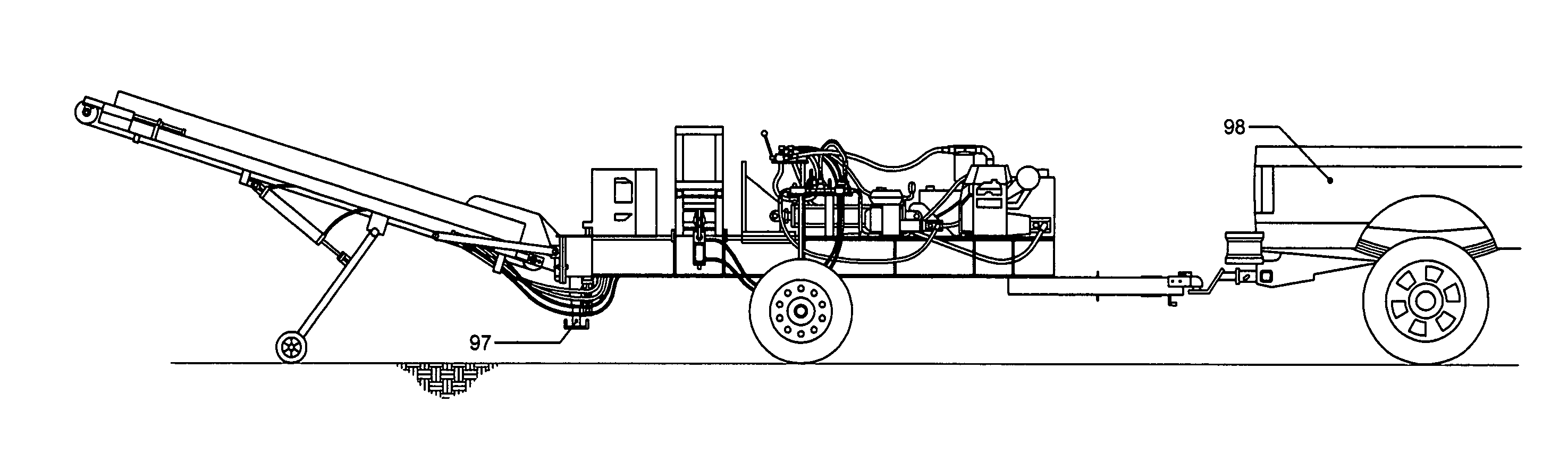
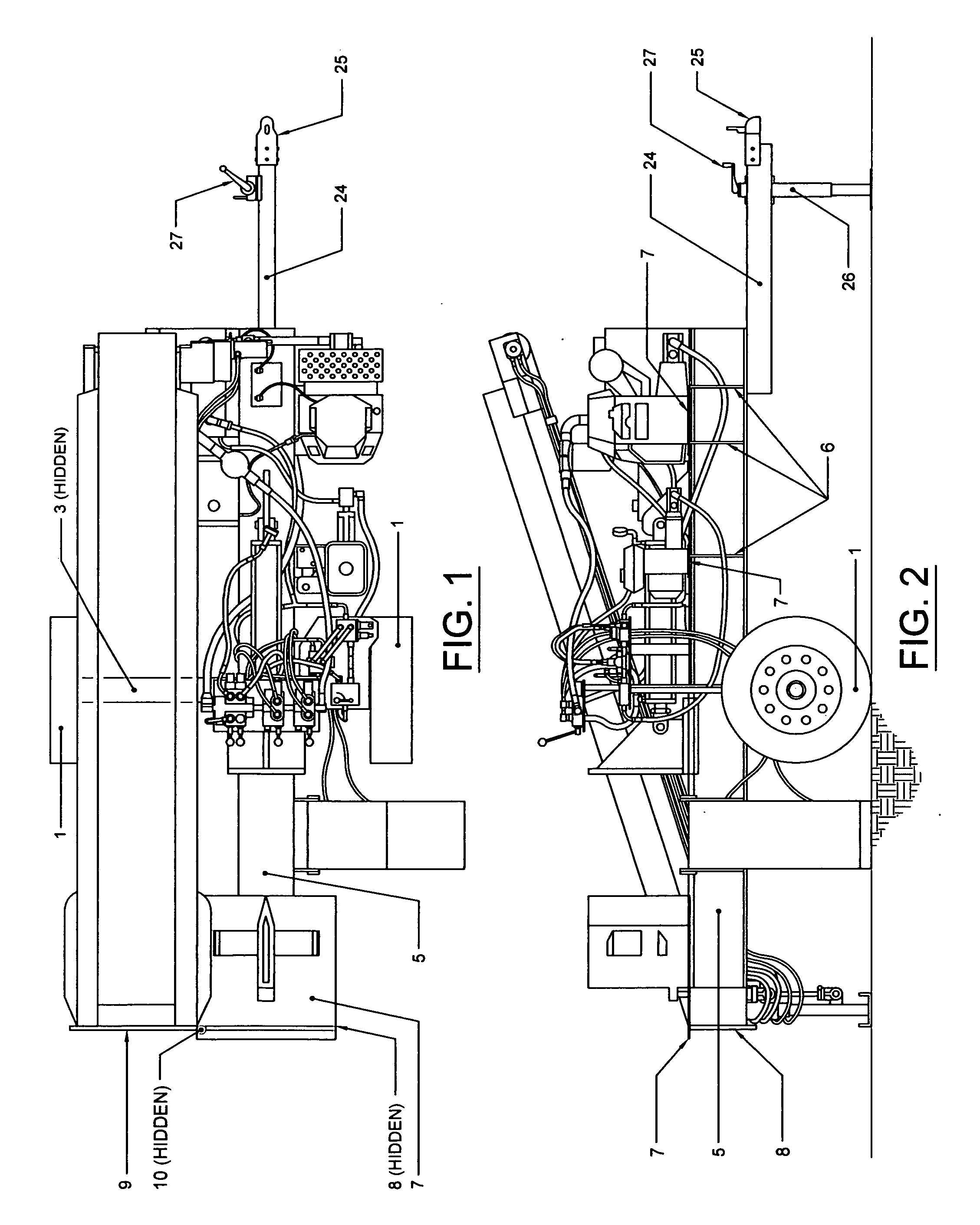
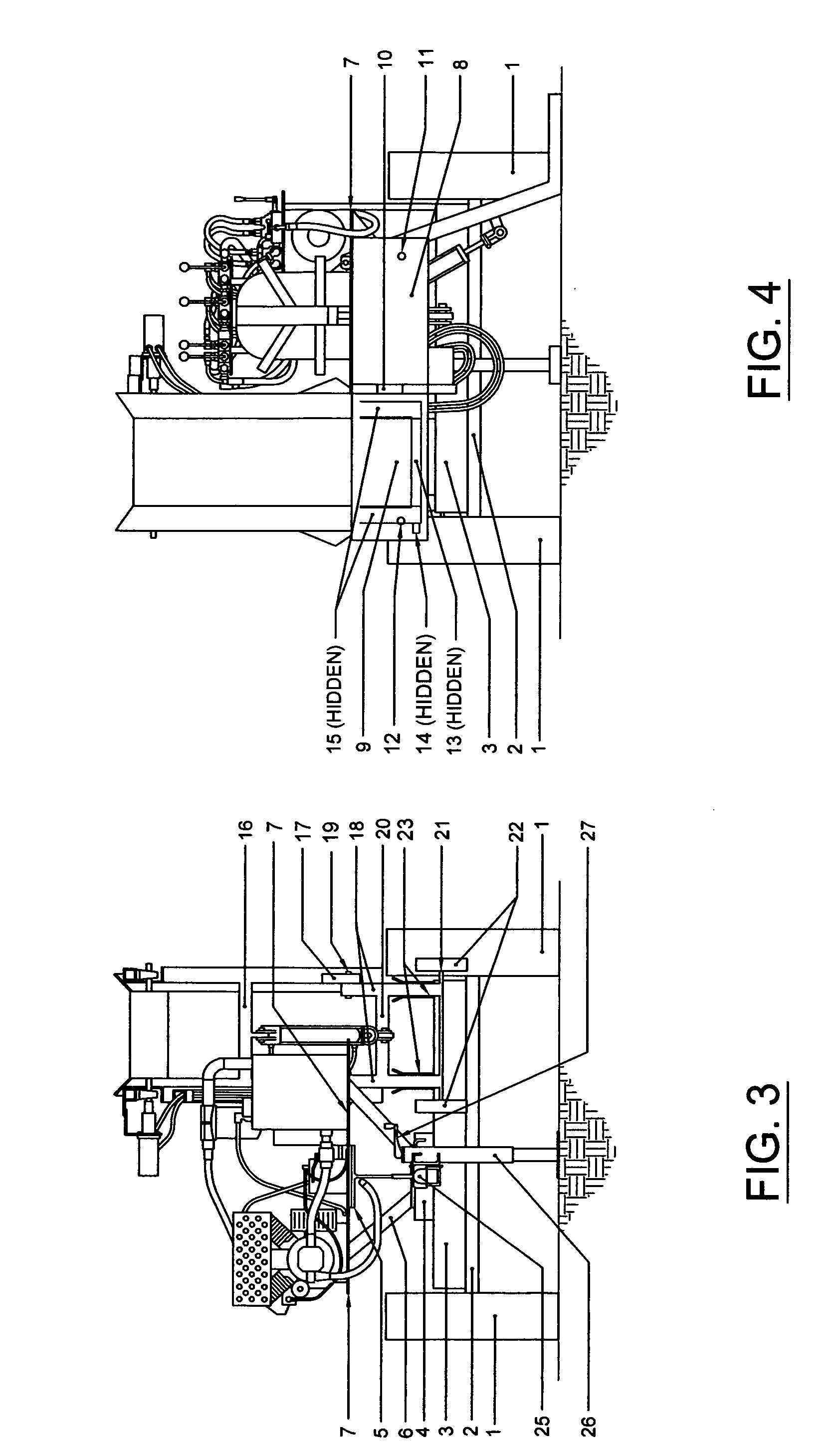
[0027]In reference to FIGS. 1, 2, 3, and 4, the development of the present invention begins with a pair of wheels 1, linked to one another by an axle which is housed in axle sleeve 2. Axle support beam 3 is then welded to the axle sleeve along its entire length, so as to provide a rigid and square connection point for the framework of the machine. Steel spacer 4 is welded to the top of axle support beam 3, and it is upon this spacer that steel I-beam 5 is centered and welded. Angle supports 6 are then welded to the bottom flange of steel I-beam 5, providing many additional support points for the subsequent welded attachment of steel plates 7. The combination of these steel plates and the top flange of steel I-beam 5, provides the supported surface upon which all the components of the horizontally oriented log splitter system are ...


PUM


Abstract

A log splitter machine featuring a steel beam upon which an engine, a hydraulic fluid reservoir, a hydraulic cylinder, a splitting ram, and a splitting head are positioned in such a way as to accomplish the task of reducing large sections of logs into smaller pieces. Additional components include a log lifter device, a telescoping rear foot, and a conveyor mechanism. The conveyor mechanism is connected to the frame of the machine by means of a hinge. The machine has both a non-operational position and an operational position. The operational position is achieved by pivoting the conveyor mechanism through an angle of one-hundred eighty degrees around the hinge. In both its non-operational and operational positions, the machine sits upon wheels, allowing for quick and easy relocation.

Description

[0001]CROSS-REFERENCE TO RELATED APPLICATIONS5,022,445June, 1991Holestine4,615,366October, 1986Scarbrough, Jr.4,481,988November, 1984Watson, et al.STATEMENT REGARDING FEDERALLY SPONSORED RESEARCH OR DEVELOPMENT[0002]Not ApplicableREFERENCE TO SEQUENCE LISTING, A TABLE, OR A COMPUTER PROGRAM LISTING COMPACT DISC APPENDIX[0003]Not ApplicableBACKGROUND OF THE INVENTION[0004]1. Field of Endeavor[0005]The present invention pertains to the general field of log splitters, more specifically to those log splitters which are of a horizontal orientation, wherein a hydraulically powered splitting ram is utilized for the purpose of forcing a log section through one or more splitting blades.[0006]2. Prior Art[0007]Many variations of horizontally oriented log splitters have been developed over time, however nearly all of them feature the same conceptual design. This design generally consists of a steel beam upon which an engine, a hydraulic fluid reservoir, a hydraulic cylinder, a splitting ram, a...

Claims


Application Information

Patent Timeline
IPC IPC(8): B27L7/06
CPCB27L7/00
Inventor SHAEFFER, LOUIS MARTIN
Owner SHAEFFER LOUIS MARTIN
Why Eureka
Try Eureka